Nissan Juke Service and Repair Manual : Front fender
Exploded View
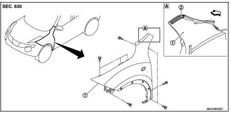
1. Front fender assembly 2. Front fender stiffener
 : Vehicle front
Removal and Installation
REMOVAL
1. Remove front fillet molding. Refer to EXT-26, "FRONT FILLET MOLDING : Removal and Installation".
2. Remove front bumper fascia assembly. Refer to EXT-13, "Removal and Installation".
3. Remove sill cover. Refer to EXT-23, "Removal and Installation".
4. Remove fender protector. Refer to EXT-22, "Removal and Installation".
5. Remove front fender cover. Refer to EXT-20, "Exploded View".
6. Remove front combination lamp. Refer to EXL-91, "Removal and Installation".
7. Remove side turn signal lamp. Refer to EXL-98, "Removal and Installation".
8. Remove mounting bolts of front fender assembly.
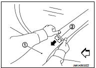
9. Remove front fender stiffener (2) from the vehicle body while carefully pulling upper portion of front fender (1) toward vehicle outside.
 : Vehicle front
10. Remove front fender assembly.
CAUTION:
An viscous urethane foam is installed on the back surface of front fender. When
removing the
front fender, be careful to not deform the front fender while performing the
procedure and removing
the viscous urethane foam a little at a time.
INSTALLATION
Note the following items, and install in the reverse order of removal.
CAUTION:
• After installation, apply the touch-up paint (the body color) onto the head of
front fender mounting
bolts.
• After installation, adjust the following part.
- Hood assembly: Refer to DLK-556, "HOOD ASSEMBLY : Adjustment".
- Front door: Refer to DLK-570, "DOOR ASSEMBLY : Adjustment".
 Radiator core supporT
HR16DE
HR16DE : Exploded View
1. Radiator core support upper
2. Air guide RH (MT models)
3. Radiator core support lower
4. Air guide LH
5. Air guide (upper)
6. Air guide LH (CVT models)
...
 Front door
Exploded View
1. Front door panel
2. Grommet
3. TORX bolt
4. Door striker
5. Door pad
6. Bumper rubber
7. Door check link
8. Door hinge (lower)
9. Door hinge (upper)
10. Grommet
: D ...
Other materials:
P1652 starter motor system COMM
Description
ECM controls ON/OFF state of the starter relay, according to the engine and
vehicle condition. Models with no
Intelligent Key System transmit a control signal directly to IPDM E/R. On the
other hand, models with the Intelligent
Key System transmit a control signal to IPDM E/R by w ...
Wiring diagram
DOOR & LOCK SYSTEM
Wiring Diagram
For connector terminal arrangements, harness layouts, and alphabets in a
(option abbreviation; if not
described in wiring diagram), refer to GI-12, "Connector Information/Explanation
of Option Abbreviation".
...
Diagnosis system (combination meter)
Consult-III Function
CONSULT-III APPLICATION ITEMS
CONSULT-III can perform the following diagnosis modes via CAN communication
and the combination meter.
SELF DIAG RESULT
Refer to MWI-36, "DTC Index".
DATA MONITOR
Display Item List
• *1: CVT models
• *2: M/T models
• ...
