Nissan Juke Service and Repair Manual : Radiator core supporT
HR16DE
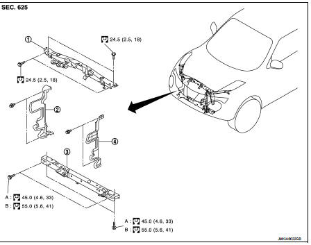
HR16DE : Exploded View
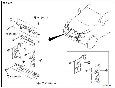
1. Radiator core support upper
2. Air guide RH (MT models)
3. Radiator core support lower
4. Air guide LH
5. Air guide (upper)
6. Air guide LH (CVT models)
7. Air guide RH (CVT models)
 : N·m (kg-m, ft-lb)
HR16DE : Removal and Installation
RADIATOR CORE SUPPORT UPPER
Removal
1. Remove front bumper fascia. Refer to EXT-13, "Removal and Installation".
2. Remove front combination lamp (LH and RH). Refer to EXL-91, "Removal and Installation".
3. Remove headlamp (LH and RH). Refer to EXL-89, "Removal and Installation".
4. Disconnect crash zone sensor harness connector. Refer to SR-26, "Removal and Installation".
CAUTION:
Turn ignition switch OFF, disconnect battery negative terminal and then wait for
at least 3 minutes.
5. Remove hood lock and hood lock cable fixing clip. Refer to DLK-587, "HOOD LOCK CONTROL CABLE : Removal and Installation".
6. Remove horn bracket. Refer to HRN-4, "Removal and Installation".
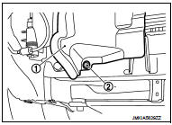
7. Remove air guide (upper) fixing clips, and then remove air guide (upper).
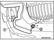
8. Remove upper fixing clips (2) of air guide (LH and RH) (1).
9. Remove hood support rod. Refer to DLK-560, "HOOD SUPPORT ROD : Removal and Installation".
10. Remove mounting bolts, and then remove radiator core support upper.
Installation Install in the reverse order of removal.
RADIATOR CORE SUPPORT LOWER
Removal
1. Remove front bumper fascia. Refer to EXT-13, "Removal and Installation".
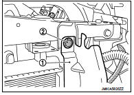
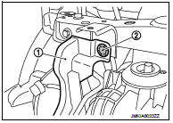
2. Remove lower fixing clips (2) of radiator side seal (LH and RH) (1).
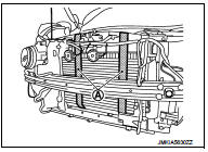
3. Use belts (A) to suspend radiator and condenser to prevent them from falling.
CAUTION:
Never damage radiator and condenser.
4. Remove mounting bolts, and then remove radiator core support lower.
Installation
Install in the reverse order of removal.
MR16DDT
MR16DDT : Exploded View
1. Radiator core support upper
2. Air guide RH
3. Radiator core support lower
4. Air guide LH
A : 2WD models
B : 4WD models
 : N·m (kg-m, ft-lb)
MR16DDT : Removal and Installation
RADIATOR CORE SUPPORT UPPER
Removal
1. Remove front bumper fascia. Refer to EXT-13, "Removal and Installation".
2. Remove front combination lamp (LH and RH). Refer to EXL-91, "Removal and Installation".
3. Remove headlamp (LH and RH). Refer to EXL-89, "Removal and Installation".
4. Disconnect crash zone sensor harness connector. Refer to SR-26, "Removal and Installation".
CAUTION:
Turn ignition switch OFF, disconnect battery negative terminal and then wait for
at least 3 minutes.
5. Remove hood lock and hood lock cable fixing clip. Refer to DLK-587, "HOOD LOCK CONTROL CABLE : Removal and Installation".
6. Remove horn bracket. Refer to HRN-4, "Removal and Installation".
7. Remove upper fixing clips (2) of air guide (LH and RH) (1).
8. Remove hood support rod. Refer to DLK-560, "HOOD SUPPORT ROD : Removal and Installation".
9. Remove mounting bolts, and then remove radiator core support upper.
Installation Install in the reverse order of removal.
RADIATOR CORE SUPPORT LOWER
Removal
1. Remove front bumper fascia. Refer to EXT-13, "Removal and Installation".
2. Remove lower fixing clips (2) of radiator side seal (LH and RH) (1).
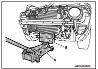
3. Using strings (A), hang inlet hose (1) and inlet hose (2) together with charge air cooler.
CAUTION:
Never damage inlet hoses with charge air cooler.
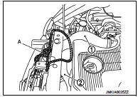
4. Support lower side radiator using wooden blocks (B) and a floor jack (A).
CAUTION:
Never damage radiator
5. Remove mounting bolts, and then remove radiator core support lower.
Installation
Install in the reverse order of removal.
 Hood
Hood
Exploded View
1. Hood assembly
2. Hood bumper rubber
3. Radiator core seal
4. Hood bumper rubber
5. Clamp
6. Hood hinge
7. Grommet
8. Hood support rod
: Clip
: Pawl
: Body grease
Ho ...
 Front fender
Exploded View
1. Front fender assembly
2. Front fender stiffener
: Vehicle front
Removal and Installation
REMOVAL
1. Remove front fillet molding. Refer to EXT-26, "FRONT FILLET MOLDING : ...
Other materials:
Structure and operation
Sectional View
1. 5th input gear
2. 5th-reverse synchronizer hub assembly
3. Input shaft
4. Mainshaft
5. 5th main gear
6. Mainshaft rear bearing
7. 4th main gear
8. 3rd-4th synchronizer hub assembly
9. 3rd main gear
10. 2nd main gear
11. 1st-2nd synchronizer hub assembly
12. Dif ...
Ecu diagnosis informatioN
TCM
Reference Value
VALUES ON THE DIAGNOSIS TOOL
*1: Means CVT fluid temperature. Convert numerical values for actual fluid
temperature °C (°F). Refer to TM-128, "ATFTEMP COUNT
Conversion Table".
TERMINAL LAYOUT
PHYSICAL VALUES
*1: This harness is not used.
*2: ...
Front wiper motor hi circuit
Component Function Check
1.CHECK FRONT WIPER HI OPERATION
CONSULT-III ACTIVE TEST
1. Select “FRONT WIPER” of IPDM E/R active test item.
2. With operating the test item, check front wiper operation.
Hi : Front wiper (HI) operation
Off : Stop the front wiper
Is front wiper (HI) operation normal ...
