Nissan Juke Service and Repair Manual : Exhaust manifold
Exploded View
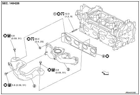
1. Stud bolt
2. Exhaust manifold cover
3. Exhaust manifold
4. Gasket
 Engine front
 : N·m (kg-m, ft-lb)
 : N·m (kg-m, in-lb)
 : Always replace after every
disassembly.
Removal and Installation
REMOVAL
1. Drain engine coolant. Refer to CO-11, "Draining".
2. Remove turbocharger. Refer to EM-36, "Exploded View".
3. Remove catalyst convertor. Refer to EM-33, "2WD : Exploded View" (2WD models) or EM-34, "4WD : Exploded View" (4WD models).
4. Remove exhaust manifold cover.
5. Remove exhaust manifold.
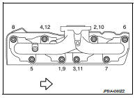
• Loosen nuts in reverse order as shown in the figure.
 : Engine front
NOTE:
Disregard the numerical order No. 9 to 12 in removal.
6. Remove gasket.
CAUTION:
Cover engine openings to avoid entry of foreign materials.
INSTALLATION
1. Install gasket to cylinder head as shown in the figure.
: Engine front
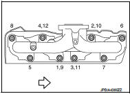
2. Install exhaust manifold with the following procedure: a. Tighten nuts in numerical order as shown in the figure.
: Engine front
NOTE
:
• Tighten nuts the No.1 to No.4 in two steps.
• The numerical order No.9 to No.12 shows the second step.
3. Install remaining parts in the reverse order of removal.
Inspection
INSPECTION AFTER REMOVAL
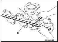
Surface Distortion
• Using feeler gauge (A) and straightedge (B), check the surface distortion
of exhaust manifold mating surface in each exhaust port
and entire part.
Limit : Refer to EM-130, "Exhaust Manifold".
• If it exceeds the limit, replace exhaust manifold.
 Turbocharger
Exploded View
1. Heat insulator
2. Actuator hose
3. Clamp
4. Turbocharger inlet tube
5. Gasket
6. Gasket
7. Clamp
8. Oil outlet hose
9. Oil return pipe
10. Oil supply tube
11. O-ri ...
 Oil pan (lower)
Exploded View
1. O-ring
2. Oil pan (upper)
3. Oil level gauge guide
4. O-ring
5. Oil level gauge
6. Oil pump drive chain
7. Crankshaft sprocket
8. Oil pump sprocket
9. Oil pump chain ...
Other materials:
Instrument panel assembly
Exploded View
LHD models
1. Front passenger air bag module
2. Instrument panel assembly
3. Instrument side finisher LH
4. Combination meter
5. Cluster lid A
6. Push-button ignition switch
7. Steering column upper cover
8. Steering lock escutcheon
9. Steering column lower cover
10. ...
Precaution for Supplemental Restraint System (SRS) "AIR BAG" and "SEAT BELT
PRE-TENSIONER"
The Supplemental Restraint System such as “AIR BAG” and “SEAT BELT PRE-TENSIONER”,
used along
with a front seat belt, helps to reduce the risk or severity of injury to the
driver and front passenger for certain
types of collision. Information necessary to service the system safely is
include ...
Precaution Necessary for Steering Wheel Rotation
after Battery Disconnect
NOTE:
• Before removing and installing any control units, first turn the push-button
ignition switch to the LOCK position,
then disconnect both battery cables.
• After finishing work, confirm that all control unit connectors are connected
properly, then re-connect both
battery cables.
• Alw ...
