Nissan Juke Service and Repair Manual : Turbocharger
Exploded View
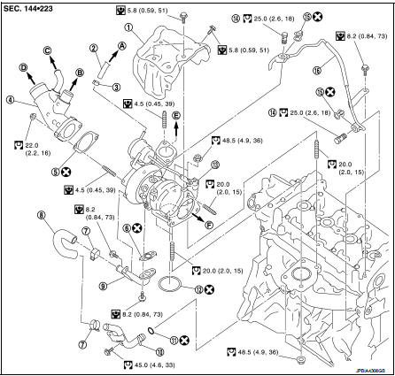
1. Heat insulator
2. Actuator hose
3. Clamp
4. Turbocharger inlet tube
5. Gasket
6. Gasket
7. Clamp
8. Oil outlet hose
9. Oil return pipe
10. Oil supply tube
11. O-ring
12. O-ring
13. Turbocharger
14. Eye bolt
15. Gasket
16. Oil supply tube
A. To EVAP canister purge volume control
solenoid valve
B. To air inlet hose
C. To PCV hose
D. To air duct E. To air inlet tube assembly F. To catalyst convertor
 : N·m (kg-m, ft-lb)
 : N·m (kg-m, in-lb)
 : Always replace after every
disassembly.
Removal and Installation
REMOVAL
1. Drain engine coolant. Refer to CO-11, "Draining".
2. Remove engine cover. Refer to EM-25, "Exploded View".
3. Remove air cleaner cover assembly and air cleaner body assembly. Refer to EM-26, "Exploded View".
4. Remove air inlet tube assembly. Refer to EM-31, "Exploded View".
5. Remove cowl top extension. Refer to EXT-20, "Exploded View".
6. Disconnect heated oxygen sensor 2 harness connector.
7. Remove front tube. Refer to EX-5, "Exploded View".
8. Remove catalyst convertor. Refer to EM-33, "2WD : Exploded View" (2WD models) or EM-34, "4WD : Exploded View" (4WD models).
9. Remove turbocharger assembly as follows:
a. Remove heat insulator.
b. Remove oil supply tube.
c. Remove mounting nuts of turbocharger.
CAUTION:
Be careful not to deform each turbocharger piping when pulling out the assembly.
INSTALLATION
Install in the reverse order of removal.
NOTE
:
Apply LOCTITE FRENETANCH or equivalent to the threads of the turbocharger oil inlet pipe union to the cylinder head
Inspection
Turbocharger
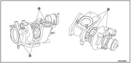
A. Check for leakage
CAUTION:
When the compressor wheel, turbine wheel or rotor shaft is damaged, remove all
the fragments and
foreign matter left in the following passages in order to prevent a secondary
failure:
Suction side : Between turbocharger and air cleaner Exhaust side : Between turbocharger and outlet duct
INSPECTION AFTER INSTALLATION
Start engine and raise engine speed to check no exhaust emission leaks.
 Catalyst
2WD
2WD : Exploded View
1. A/F sensor 1
2. Catalyst convertor shroud upper
3. Gasket
4. Catalyst
5. Catalyst convertor support bracket rear
6. Catalyst convertor bracket (RH)
A. To exhau ...
 Exhaust manifold
Exploded View
1. Stud bolt
2. Exhaust manifold cover
3. Exhaust manifold
4. Gasket
Engine front
: N·m (kg-m, ft-lb)
: N·m (kg-m, in-lb)
: Always replace after every
disassembly.
Remova ...
Other materials:
P0172 fuel injection system function
DTC Logic
DTC DETECTION LOGIC
With the Air/Fuel Mixture Ratio Self-Learning Control, the actual mixture
ratio can be brought closely to the
theoretical mixture ratio based on the mixture ratio feedback signal from the
A/F sensor 1. The ECM calculates
the necessary compensation to correct the ...
Rear door
Exploded View
1. Rear door panel
2. Door hinge (upper)
3. Door hinge (lower)
4. Door check link
5. Door striker
6. TORX bolt
: Do not reuse
: N·m (kg-m, in-lb)
: N·m (kg-m, ft-lb)
: Body grease
DOOR ASSEMBLY
DOOR ASSEMBLY : Removal and Installation
CAUTION:
• Perform work with 2 ...
Precaution for Supplemental Restraint System (SRS) "AIR BAG" and "SEAT BELT
PRE-TENSIONER"
The Supplemental Restraint System such as “AIR BAG” and “SEAT BELT PRE-TENSIONER”,
used along
with a front seat belt, helps to reduce the risk or severity of injury to the
driver and front passenger for certain
types of collision. Information necessary to service the system safely is
include ...
