Nissan Juke Service and Repair Manual : Door lock and unlock switch
Driver side : Component Function Check
1.CHECK FUNCTION
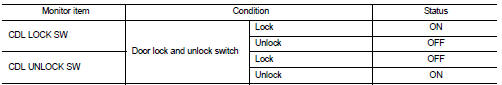
1. Select “DOOR LOCK” of “BCM” using CONSULT-III.
2. Select “CDL LOCK SW”, “CDL UNLOCK SW” in “DATA MONITOR” mode.
3. Check that the function operates normally according to the following conditions.
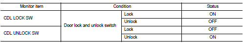
Is the inspection result normal? YES >> Door lock and unlock switch is OK.
NO >> Refer to DLK-79, "DRIVER SIDE : Diagnosis Procedure".
Driver side : Diagnosis Procedure
1.CHECK DOOR LOCK AND UNLOCK SWITCH INPUT SIGNAL
1. Turn ignition switch OFF.
2. Disconnect power window main switch connector.
3. Check signal between power window main switch harness connector and ground using oscilloscope.
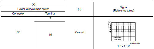
Is the inspection result normal? YES >> GO TO 3.
NO >> GO TO 2.
2.CHECK DOOR LOCK AND UNLOCK SWITCH CIRCUIT
1. Disconnect BCM connector and front power window switch (passenger side) connector.
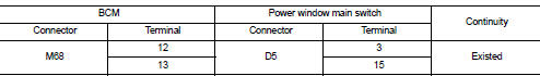
2. Check continuity between BCM harness connector and power window main switch harness connector.
3. Check continuity between BCM harness connector and ground.
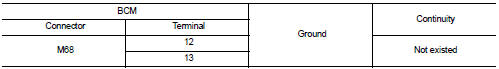
Is the inspection result normal? YES >> Replace BCM. Refer to BCS-93, "Removal and Installation".
NO >> Repair or replace harness.
3.CHECK DOOR LOCK AND UNLOCK SWITCH GROUND
Check continuity between power window main switch harness connector and ground.
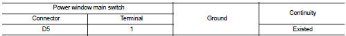
Is the inspection result normal? YES >> GO TO 4.
NO >> Repair or replace harness.
4.CHECK DOOR LOCK AND UNLOCK SWITCH
Refer to DLK-80, "DRIVER SIDE : Component Inspection".
Is the inspection result normal? YES >> GO TO 5.
NO >> Replace power window main switch. Refer to PWC-44, "Removal and Installation".
5.CHECK INTERMITTENT INCIDENT
Refer to GI-42, "Intermittent Incident".
>> INSPECTION END
Driver side : Component Inspection
1.CHECK DOOR LOCK AND UNLOCK SWITCH
1. Turn ignition switch OFF.
2. Disconnect power window main switch connector.
3. Check continuity between power window main switch terminals.
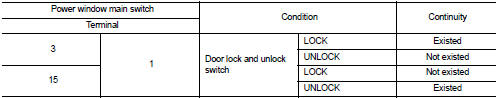
Is the inspection result normal? YES >> INSPECTION END
NO >> Replace power window main switch.
Passenger side : Component Function Check
1.CHECK FUNCTION
1. Select “DOOR LOCK” of “BCM” using CONSULT-III.
2. Select “CDL LOCK SW”, “CDL UNLOCK SW” in “DATA MONITOR” mode.
3. Check that the function operates normally according to the following conditions.
Is the inspection result normal? YES >> Door lock and unlock switch is OK.
NO >> Refer to DLK-81, "PASSENGER SIDE : Diagnosis Procedure".
Passenger side : Diagnosis Procedure
1.CHECK DOOR LOCK AND UNLOCK SWITCH INPUT SIGNAL
1. Turn ignition switch OFF.
2. Disconnect front power window switch (passenger side) connector.
3. Check signal between front power window switch (passenger side) harness connector and ground using oscilloscope.
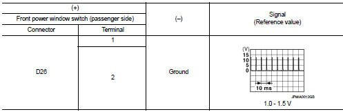
Is the inspection result normal? YES >> GO TO 3.
NO >> GO TO 2.
2.CHECK DOOR LOCK AND UNLOCK SWITCH CIRCUIT
1. Disconnect BCM connector and power window main switch connector.
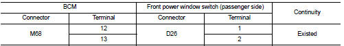
2. Check continuity between BCM harness connector and front power window switch (passenger side) harness connector.
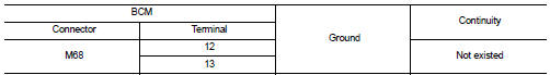
3. Check continuity between BCM harness connector and ground.
Is the inspection result normal? YES >> Replace BCM. Refer to BCS-93, "Removal and Installation".
NO >> Repair or replace harness.
3.CHECK DOOR LOCK AND UNLOCK SWITCH GROUND
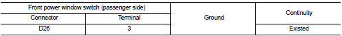
Check continuity between front power window switch (passenger side) harness connector and ground.
Is the inspection result normal? YES >> GO TO 4.
NO >> Repair or replace harness.
4.CHECK DOOR LOCK AND UNLOCK SWITCH
Refer to DLK-82, "PASSENGER SIDE : Component Inspection".
Is the inspection result normal? YES >> GO TO 5.
NO >> Replace front power window switch (passenger side). Refer to PWC-44, "Removal and Installation".
5.CHECK INTERMITTENT INCIDENT
Refer to GI-42, "Intermittent Incident".
>> INSPECTION END
Passenger side : Component Inspection
1.CHECK DOOR LOCK AND UNLOCK SWITCH
1. Turn ignition switch OFF.
2. Disconnect front power window switch (passenger side) connector.
3. Check continuity between front power window switch (passenger side) terminals.
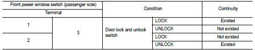
Is the inspection result normal? YES >> INSPECTION END
NO >> Replace front power window switch (passenger side).
 Door lock actuator
Driver side : Component Function Check
1.CHECK FUNCTION
1. Select “DOOR LOCK” of “BCM” using CONSULT-III.
2. Select “DOOR LOCK” in “ACTIVE TEST” mode.
3. Check that the function operates normally ...
 Door lock status indicator
Component Function Check
1.CHECK FUNCTION
1. Select “DOOR LOCK” of “BCM” using CONSULT-III.
2. Select “DOOR LOCK IND” in “ACTIVE TEST” mode.
3. Check that the function operates normally according ...
Other materials:
Cooling fan control
Cooling fan control : System Diagram
Cooling fan control : System Description
INPUT/OUTPUT SIGNAL CHART
*: The ECM determines the start signal status by the signals of engine speed
and battery voltage.
SYSTEM DESCRIPTION
ECM controls cooling fan speed corresponding to vehicle speed, eng ...
Front door
Exploded View
1. Front door panel
2. Grommet
3. TORX bolt
4. Door striker
5. Door pad
6. Bumper rubber
7. Door check link
8. Door hinge (lower)
9. Door hinge (upper)
10. Grommet
: Do not reuse
: N·m (kg-m, in-lb)
: N·m (kg-m, ft-lb)
: Body grease
Door assembly
DOOR ASSEMBLY : ...
Remove
Use the following procedure to remove the head restraint/headrest.
1. Pull the head restraint/headrest up to the highest position.
2. Push and hold the lock knob.
3. Remove the head restraint/headrest from the seat.
4. Store the head restraint/headrest properly in a secure place so it is not l ...
