Nissan Juke Service and Repair Manual : Cooling fan control
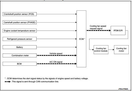
Cooling fan control : System Diagram
Cooling fan control : System Description
INPUT/OUTPUT SIGNAL CHART
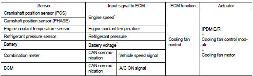
*: The ECM determines the start signal status by the signals of engine speed and battery voltage.
SYSTEM DESCRIPTION
ECM controls cooling fan speed corresponding to vehicle speed, engine coolant temperature, A/C ON signal and refrigerant pressure.
Cooling fan control signal is sent to IPDM E/R from ECM by CAN communication line. Then, IPDM E/R sends ON/OFF pulse duty signal to cooling fan control module. Corresponding to this ON/OFF pulse duty signal, cooling fan control module gives cooling fan motor operating voltage to cooling fan motors. Cooling fan speed is controlled by duty cycle of cooling fan motor operating voltage sent from cooling fan control module.
 Air conditioning cut control
Air conditioning cut control : System Diagram
Air conditioning cut control : System Description
INPUT/OUTPUT SIGNAL CHART
*: ECM determines the start signal status by the signals of engine spe ...
 Starter motor drive control
Starter motor drive control : System Diagram
Starter motor drive control : System
DescriptionINPUT/OUTPUT SIGNAL CHART
INPUT/OUTPUT SIGNAL CHART
*: With Intelligent Key system
SYSTEM DESCRIPT ...
Other materials:
Clutch master cylinder
LHD : Exploded View
1. Reservoir hose
2. Reservoir tank
3. Master cylinder
LHD : Removal and Installation
REMOVAL
CAUTION:
• Keep painted surface on the body or other parts free of clutch fluid. If it
spills, wipe up immediately
and wash the affected area with water.
• Never disassemb ...
B26F5 steering lock status switch
DTC Logic
DTC DETECTION LOGIC
NOTE:
• If DTC B26F5 is displayed with DTC U1000, first perform the trouble diagnosis
for DTC U1000. Refer to
BCS-83, "DTC Logic".
• If DTC B26F5 is displayed with DTC U1010, first perform the trouble diagnosis
for DTC U1010. Refer to
BCS-84, "D ...
P160C ECM
DTC Logic
DTC DETECTION LOGIC
Diagnosis Procedure
1.INSPECTION START
1. Turn ignition switch ON.
2. Erase DTC.
3. Turn ignition switch OFF and wait for 20 seconds.
4. Turn ignition switch ON and perform the self-diagnosis.
Is the DTC P160C displayed again?
YES >> GO TO 2.
NO &g ...
