Nissan Juke Service and Repair Manual : CVT position
Inspection and Adjustment
INSPECTION
1. Place selector lever in “P” position, and turn ignition switch ON (engine stop).
2. Make sure that selector lever can be shifted to other than “P” position when brake pedal is depressed. Also make sure that selector lever can be shifted from “P” position only when brake pedal is depressed.
3. Move the selector lever and check for excessive effort, sticking, noise or rattle.
4. Confirm the selector lever stops at each position with the feel of engagement when it is moved through all the positions. Check that the actual position of the selector lever matches the position shown by the shift position indicator and the manual lever on the transaxle.
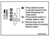
5. The method of operating the selector lever to individual positions correctly should be as shown.
6. When selector button is pressed in “P”, “R” or “N” position without applying forward/backward force to selector lever, check button operation for sticking.
7. Confirm the back-up lamps illuminate only when selector lever is placed in the “R” position. Confirm the back-up lamps do not illuminate when the selector lever is pushed toward the “R” position when in the “P” or “N” position.
8. Confirm the engine can only be started with the selector lever in the “P” and “N” positions.
9. Make sure transaxle is locked completely in “P” position.
10. When selector lever is set to manual shift gate, make sure that manual mode is displayed on combination meter.
Shift selector lever to “+” and “–” sides, and check that set shift position changes.
ADJUSTMENT
1. Place selector lever in “P” position.
CAUTION:
Turn wheels more than 1/4 rotations and apply the park lock.
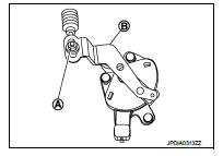
2. Loosen nut (A) and place manual lever (B) in “P” position.
CAUTION:
Never apply any force to the manual lever.
3. Tighten nut. Refer to TM-273, "Removal and Installation".
CAUTION:
Fix the manual lever when tightening.
 Road test
Description
DESCRIPTION
• The purpose of the test is to determine overall performance of CVT
and analyze causes of problems.
• The road test consists of the following three parts:
1. “Check Befor ...

Other materials:
Vehicle Dynamic Control (VDC) off switch
The vehicle should be driven with the Vehicle Dynamic Control (VDC) system on
for most driving conditions.
If the vehicle is stuck in mud or snow, the VDC system reduces the engine output
to reduce wheel spin. The engine speed will be reduced even if the accelerator is
depressed to the floo ...
P1610 lock mode
Description
ECM forcibly switches to the mode that inhibits engine start, when engine
start operation is performed 5 times
or more while communication between ECM and BCM is not normal.
DTC Logic
DTC DETECTION LOGIC
DTC CONFIRMATION PROCEDURE
1.PERFORM DTC CONFIRMATION PROCEDURE
1. Turn i ...
Continuously Variable Transmission (CVT)
The Continuously Variable Transmission (CVT) in your vehicle is electronically
controlled to produce maximum power and smooth operation.
The recommended operating procedures for this transmission are shown on the following
pages.
Follow these procedures for maximum vehicle performance and driv ...
