Nissan Juke Service and Repair Manual : CSC (concentric slave cylinder)
Exploded View
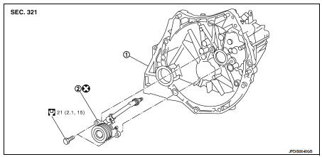
1. Transaxle assembly 2. CSC (Concentric Slave Cylinder)
 : Always replace after every
disassembly.
 : N·m (kg-m, ft-lb)
Removal and Installation
CAUTION:
• Never reuse CSC (Concentric Slave Cylinder). Because CSC slides back to the
original position
every time when removing transaxle assembly. At this timing, dust on the sliding
parts may damage
a seal of CSC and may cause clutch fluid leakage.
• Never disassemble CSC.
• Keep painted surface on the body or other parts free of clutch fluid. If it spills, wipe up immediately and wash the affected area with water.
REMOVAL
1. Remove transaxle assembly. Refer to TM-30, "Removal and Installation" (RS5F92R), or TM-84, "MR16DDT : Removal and Installation" (RS6F94R with MR16DDT), TM-86, "K9K : Removal and Installation" (RS6F94R with K9K).
2. Remove CSC from clutch housing.
INSTALLATION
1. Install CSC to clutch housing, and then tighten CSC mounting bolts to the specified torque.
CAUTION:
• Never reuse CSC.
• Never insert and operate CSC because piston and stopper of CSC components may fall off.
2. For the next step and after, install in the reverse order of removal.
Inspection and Adjustment
INSPECTION AFTER INSTALLATION
Check the fluid leakage and the fluid level. Refer to CL-10, "RS5F92R : Inspection" (RS5F92R) or CL-13, "RS6F94R : Inspection" (RS6F94R).
ADJUSTMENT AFTER INSTALLATION
Perform the air bleeding. Refer to CL-12, "RS5F92R : Air Bleeding" (RS5F92R) or CL-15, "RS6F94R : Air Bleeding" (RS6F94R).

 Clutch disc and clutch cover
Except for K9K : Exploded View
HR16DE
1. Flywheel
2. Clutch disc
3. Clutch cover
4. Input shaft
A. First step
B. Final step
: N·m (kg-m, ft-lb)
: Apply lithium-based grease
including m ...
Other materials:
Door mirror system (with intelligent key)
LHD
LHD : Wiring Diagram
For connector terminal arrangements, harness layouts, and alphabets in a
(option abbreviation; if not
described in wiring diagram), refer to GI-12, "Connector Information/Explanation
of Option Abbreviation".
RHD
RHD : Wiring Diagram
For connector termina ...
Hazard reminder operation does not operate
Diagnosis Procedure
1.CHECK DTC WITH BCM AND COMBINATION METER
Check that DTC is not detected with BCM and combination meter.
Is the inspection result normal?
YES >> GO TO 2.
NO-1 >> Refer to BCS-141, "DTC Index". (BCM)
NO-2 >> Refer to MWI-36, "DTC Index&q ...
B2615 blower relay circuit
DTC Logic
DTC DETECTION LOGIC
DTC CONFIRMATION PROCEDURE
1.PERFORM DTC CONFIRMATION PROCEDURE
1. Turn ignition switch ON under the following conditions, and wait for 1
second or more.
CVT models
- Selector lever is in the P or N position
- Do not depress brake pedal
M/T models
- Do no ...
