Nissan Juke Service and Repair Manual : Clutch pedal position switch
Component Function Check
1.CHECK CLUTCH PEDAL POSITION SWITCH FUNCTION
 With CONSULT-III
1. Turn ignition switch ON.
2. Select “ENGINE” using CONSULT-III.
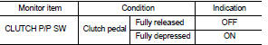
3. Select “CLUTCH P/P SW” in “DATA MONITOR” mode.
4. Check “CLUTCH P/P SW” indication under the following conditions.
 Without CONSULT-III
1. Turn ignition switch ON.
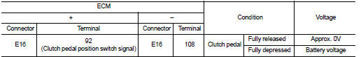
2. Check the voltage between ECM harness connector and ground.
Is the inspection result normal? YES >> INSPECTION END
NO >> Go to EC-771, "Diagnosis Procedure".
Diagnosis Procedure
1.CHECK CLUTCH PEDAL POSITION SWITCH GROUND CIRCUIT FOR OPEN AND SHORT
1. Turn ignition switch OFF.
2. Disconnect clutch pedal position switch harness connector.
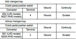
3. Check the continuity between clutch pedal position switch harness connector and ground.
4. Also check harness for short to power.
Is the inspection result normal? YES >> GO TO 2.
NO >> Repair open circuit or short to power in harness or connectors.
2.CHECK CLUTCH PEDAL POSITION SWITCH INPUT SIGNAL CIRCUIT FOR OPEN AND SHORT
1. Disconnect ECM harness connector.
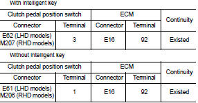
2. Check the continuity between clutch pedal position switch harness connector and ECM harness connector.
3. Also check harness for short to ground and short to power.
Is the inspection result normal? YES >> GO TO 3.
NO >> Repair open circuit or short to ground or short to power in harness or connectors.
3.CHECK CLUTCH PEDAL POSITION SWITCH
Refer to EC-772, "Component Inspection".
Is the inspection result normal? YES >> GO TO 4.
NO >> Replace clutch pedal position switch.
4.CHECK INTERMITTENT INCIDENT
Refer to GI-42, "Intermittent Incident".
>> INSPECTION END
Component Inspection
1.CHECK CLUTCH PEDAL POSITION SWITCH-I
1. Turn ignition switch OFF.
2. Disconnect clutch pedal position switch harness connector.
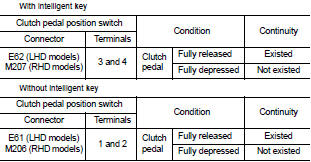
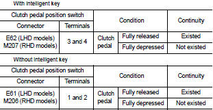
3. Check the continuity between clutch pedal position switch terminals under the following conditions.
Is the inspection result normal? YES >> INSPECTION END
NO >> GO TO 2.
2.CHECK CLUTCH PEDAL POSITION SWITCH-II
1. Adjust clutch pedal position switch installation. Refer to CL-7, "Inspection and Adjustment".
2. Check the continuity between clutch pedal position switch terminals under the following conditions.
Is the inspection result normal? YES >> INSPECTION END
NO >> Replace clutch pedal position switch.
 ASCD main switch
Component Function Check
1.CHECK ASCD MAIN SWITCH FUNCTION
With CONSULT-III
1. Turn ignition switch ON.
2. Select “ENGINE” using CONSULT-III.
3. Select “MAIN SW” in “DATA MONITOR” mode.
4. Check ...
 Cooling fan
Component Function Check
1.CHECK COOLING FAN FUNCTION
With CONSULT-III
1. Turn ignition switch ON.
2. Perform “COOLING FAN” in “ACTIVE TEST” mode with CONSULT-III.
3. Touch “LOW” and “Hi” on the ...
Other materials:
Door lock status indicator
Component Function Check
1.CHECK FUNCTION
1. Select “DOOR LOCK” of “BCM” using CONSULT-III.
2. Select “DOOR LOCK IND” in “ACTIVE TEST” mode.
3. Check that the function operates normally according to the following
conditions.
Is the inspection result normal?
YES >> Door lock status in ...
B1184 lap Pre-tensioner LH
DTC Logic
DTC CONFIRMATION PROCEDURE
1.CHECK SELF-DIAGNOSTIC RESULT
With CONSULT-III
1. Turn ignition switch ON.
2. Perform “Self Diagnostic Result” mode of “AIR BAG” using CONSULT-III.
Without CONSULT-III
1. Turn ignition switch ON.
2. Check the air bag warning lamp status. Refer to SRC ...
TCM
Exploded View
1. Bracket
2. TCM
:Vehicle front
: N·m (kg-m, in-lb)
Removal and Installation
NOTE:
When replacing TCM and transaxle assembly as a set, replace transaxle assembly
first and then replace
TCM. Refer to TM-374, "Description".
REMOVAL
1. Remove the battery. Refer ...
