Nissan Juke Service and Repair Manual : C1110, C1170 ABS actuator and electric unit (control unit)
DTC Logic
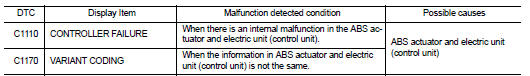
DTC DETECTION LO
DTC CONFIRMATION PROCEDURE
1.PRECONDITIONING
If “DTC CONFIRMATION PROCEDURE” has been previously conducted, always turn ignition switch OFF and wait at least 10 seconds before conducting the next test.
>> GO TO 2.
2.CHECK DTC DETECTION
 With CONSULT-III.
1. Turn the ignition switch OFF to ON.
2. Perform self-diagnosis for “ABS”.
Is DTC “C1110” or “C1170” detected? YES >> Proceed to BRC-162, "Diagnosis Procedure".
NO >> INSPECTION END
Diagnosis Procedure
1.CHECK SELF-DIAGNOSIS RESULTS
Replace ABS actuator and electric unit (control unit) even if other display than “C1110” or “C1170” is displayed in self-diagnosis for “ABS”.
>> Replace ABS actuator and electric unit (control unit). Refer to BRC-233, "Removal and Installation".
 C1109 power and ground system
DTC Logic
DTC DETECTION LOGIC
DTC CONFIRMATION PROCEDURE
1.PRECONDITIONING
If “DTC CONFIRMATION PROCEDURE” has been previously conducted, always turn
ignition switch OFF and
wait at least 10 ...
 C1111 ABS motor, motor relay system
DTC Logic
DTC DETECTION LOGIC
DTC CONFIRMATION PROCEDURE
1.PRECONDITIONING
If “DTC CONFIRMATION PROCEDURE” has been previously conducted, always turn
ignition switch OFF and
wait at least 10 ...
Other materials:
P2127, P2128 APP sensor
DTC Logic
DTC DETECTION LOGIC
DTC CONFIRMATION PROCEDURE
1.PRECONDITIONING
If DTC Confirmation Procedure has been previously conducted, always perform
the following procedure
before conducting the next test.
1. Turn ignition switch OFF and wait at least 10 seconds.
2. Turn ignition swit ...
P0525 ASCD system
DTC Logic
DTC DETECTION LOGIC
Diagnosis Procedure
1.CHECK GROUND CONNECTIONS
1. Turn ignition switch OFF and wait at least 20 seconds.
2. Check ground connection E38. Refer to Ground inspection in GI-44, "Circuit
Inspection".
Is the inspection result normal?
YES >> GO TO ...
System
Can communication system
CAN COMMUNICATION SYSTEM : System Diagram
CAN COMMUNICATION SYSTEM : System Description
Description
• CAN (Controller Area Network) is a serial communication line for real time
application. It is an on-vehicle
multiplex communication line with high data communicatio ...
