Nissan Juke Service and Repair Manual : Basic inspection
DIAGNOSIS AND REPAIR WORKFLOW (METER SYSTEM)
Work flow
OVERALL SEQUENCE
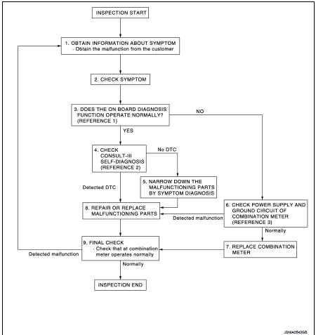
• Reference 1···MWI-22, "On Board Diagnosis Function".
• Reference 2···MWI-36, "DTC Index".
• Reference 3···MWI-51, "COMBINATION METER : Diagnosis Procedure".
DETAILED FLOW
1.OBTAIN INFORMATION ABOUT SYMPTOM
Interview the customer to obtain as much information as possible about the conditions and environment under which the malfunction occurred.
>> GO TO 2.
2.CHECK SYMPTOM
• Check the symptom based on the information obtained from the customer.
• Check that any other malfunctions are present.
>> GO TO 3.
3.CHECK ON BOARD DIAGNOSIS OPERATION
Check that the on board diagnosis function operates. Refer to MWI-22, "On Board Diagnosis Function".
Does the on board diagnosis function operate normally? YES >> GO TO 4.
NO >> GO TO 6.
4.CHECK CONSULT-III SELF-DIAGNOSIS RESULTS
Connect CONSULT-III and perform self-diagnosis. Refer to MWI-36, "DTC Index".
Are self-diagnosis results normal? YES >> GO TO 5.
NO >> GO TO 8.
5.NARROW DOWN THE MALFUNCTIONING PARTS BY SYMPTOM DIAGNOSIS
Perform symptom diagnosis and narrow down the malfunctioning parts.
>> GO TO 8.
6.CHECK COMBINATION METER POWER SUPPLY AND GROUND CIRCUITS
Check combination meter power supply and ground circuits. Refer to MWI-51, "COMBINATION METER : Diagnosis Procedure".
Is inspection result OK? YES >> GO TO 7.
NO >> GO TO 8.
7.REPLACE COMBINATION METER
Replace combination meter.
>> GO TO 9.
8.REPAIR OR REPLACE MALFUNCTIONING PARTS
Repair or replace the malfunctioning parts.
NOTE
:
If DTC is displayed, erase DTC after repair or replace malfunctioning parts.
>> GO TO 9.
9.FINAL CHECK
Check that the combination meter operates normally.
Do they operate normally? YES >> INSPECTION END
NO >> GO TO 1.
 Wiring diagram
METER SYSTEM
Wiring Diagram
For connector terminal arrangements, harness layouts, and alphabets in a
(option abbreviation; if not
described in wiring diagram), refer to GI-12, "Connector Info ...

Other materials:
Manual Transmission (MT)
WARNING
• Do not downshift abruptly on slippery roads. This may cause a loss
of control.
• Do not over-rev the engine when shifting to a lower gear. This may cause a loss
of control or engine damage.
• When the high fluid temperature protection mode or fail-safe operation occurs,
vehi ...
Diagnosis and repair work flow
Work Flow
OVERALL SEQUENCE
Reference 1··· Refer to AV-77, "Symptom Table".
DETAILED FLOW
1.CHECK SYMPTOM
Check the malfunction symptoms by performing the following items.
• Interview the customer to obtain the malfunction information (conditions and
environment when the malfu ...
Filament
Inspection and Repair
INSPECTION
1. When measuring voltage, wrap tin foil around the top of the negative
probe. Then press the foil against the wire with your finger.
2. Attach probe circuit tester (in Volt range) to middle portion of
each filament.
3. If a filament is burned out, circuit ...
