Nissan Juke Service and Repair Manual : Back door opener actuator
Diagnosis Procedure
1.CHECK BACK DOOR OPENER ACTUATOR INPUT SIGNAL
1. Turn ignition switch OFF.
2. Disconnect back door opener assembly connector.
3. Check voltage between back door opener assembly harness connector and ground.
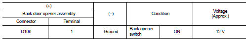
Is the inspection result normal? YES >> GO TO 3.
NO >> GO TO 2.
2.CHECK BACK DOOR OPENER ACTUATOR CIRCUIT
1. Disconnect BCM connector.
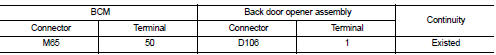
2. Check continuity between BCM harness connector and back door opener assembly harness connector.
3. Check continuity between BCM harness connector and ground.
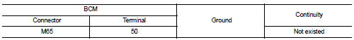
Is the inspection result normal? YES >> Replace BCM. Refer to BCS-161, "Removal and Installation".
NO >> Repair or replace harness.
3.CHECK BACK DOOR OPENER ACTUATOR GROUND CIRCUIT
Check continuity between back door opener assembly harness connector and ground.
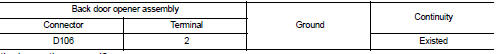
Is the inspection normal? YES >> Replace back door opener assembly.
NO >> Repair or replace harness.

 Back door opener switch
Component Function Check
1.CHECK FUNCTION
1. Select “TRUNK” of “BCM” using CONSULT-III.
2. Select “TRNK OPNR SW” in “DATA MONITOR” mode.
3. Check that the function operates normally according to t ...
Other materials:
P047B exhaust gas pressure sensor 2
DTC Logic
DTC DETECTION LOGIC
Diagnosis Proce
1.CHECK GROUND CONNECTIONS
1. Turn ignition switch OFF and wait at least 20 seconds.
2. Check ground connection E38. Refer to Ground inspection in GI-44, "Circuit
Inspection".
Is the inspection result normal?
YES >> GO TO 2.
...
U1000 can comm circuit
Description
CAN (Controller Area Network) is a serial communication system for real time
application. It is an on-vehicle
multiplex communication system with high data communication speed and excellent
error detection ability.
Many electronic control units are equipped onto vehicles, and ea ...
Front oil seal
FRONT OIL SEAL : Removal and Installation
REMOVAL
1. Remove the following parts.
• Front fender protector (RH): Refer to EXT-22, "Exploded View".
• Drive belt: Refer to EM-20, "Exploded View".
• Crankshaft pulley: Refer to EM-67, "Exploded View".
2. Remove front ...
