Nissan Juke Service and Repair Manual : B2614 ACC relay circuit
DTC Logic
DTC DETECTION LOGIC
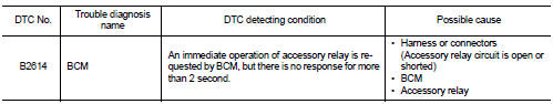
DTC CONFIRMATION PROCEDURE
1.PERFORM DTC CONFIRMATION PROCEDURE
1. Turn the power supply position to ACC under the following conditions, and wait for 2 second or more.
CVT models
- Selector lever is in the P or N position
- Do not depress brake pedal
M/T models
- Do not depress clutch pedal
2. Check “Self-diagnosis result” of BCM with CONSULT-III.
Is DTC detected? YES >> Go to PCS-91, "Diagnosis Procedure".
NO >> INSPECTION END
Diagnosis Procedure
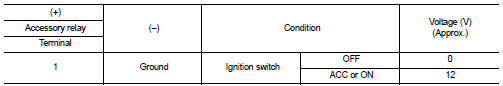
1.CHECK ACCESSORY RELAY POWER SUPPLY-1
1. Turn ignition switch OFF.
2. Disconnect accessory relay.
3. Check voltage between accessory relay harness connector and ground.
Is the inspection result normal? YES >> GO TO 3.
NO >> GO TO 2.
2.CHECK ACCESSORY RELAY POWER SUPPLY CIRCUIT
1. Turn ignition switch OFF.
2. Disconnect BCM connector.
3. Check continuity between accessory relay harness connector and BCM harness connector.

4. Check continuity between accessory relay harness connector and ground.
Is the inspection result normal? YES >> Replace BCM. Refer to BCS-93, "Removal and Installation".
NO >> Repair or replace harness.
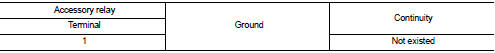
3.CHECK ACCESSORY RELAY GROUND CIRCUIT
1. Turn ignition switch OFF.
2. Check continuity between accessory relay harness connector and ground.

Is the inspection result normal? YES >> GO TO 4.
NO >> Repair accessory relay ground circuit.
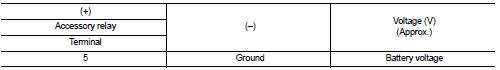
4.CHECK ACCESSORY RELAY POWER SUPPLY CIRCUIT-2
1. Turn ignition switch ACC.
2. Check voltage between accessory relay harness connector and ground.
Is the inspection result normal? YES >> GO TO 5.
NO >> Check continuity open or short between accessory relay and battery.
5.CHECK ACCESSORY RELAY
Refer to PCS-92, "Component Inspection".
Is the inspection result normal? YES >> GO TO 6.
NO >> Replace accessory relay.
6.CHECK INTERMITTENT INCIDENT
Refer to GI-42, "Intermittent Incident".
>> INSPECTION END
Component Inspection
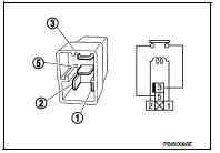
1.CHECK ACCESSORY RELAY
1. Turn ignition switch OFF.
2. Remove accessory relay.
3. Check the continuity between accessory relay terminals.
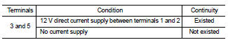
Is the inspection result normal? YES >> INSPECTION END
NO >> Replace accessory relay

 B2615 blower relay circuit
DTC Logic
DTC DETECTION LOGIC
DTC CONFIRMATION PROCEDURE
1.PERFORM DTC CONFIRMATION PROCEDURE
1. Turn ignition switch ON under the following conditions, and wait for 1
second or more.
CVT m ...
Other materials:
S terminal circuit
Description
The starter motor magnetic switch is supplied with power when the ignition
switch is turned to the START position
while the selector lever is in the P or N position for CVT models or the clutch
pedal is depressed for M/T
models.
Diagnosis Procedure
CAUTION:
Perform diagnosis un ...
Integrated control system (if so equipped)
The Integrated Control System is located below the audio system or navigation
system (if so equipped). Two Integrated Control System modes can be selected: Drive
mode and Climate Control mode.
Depending on which Integrated Control System mode selected (Drive mode or Climate
Control mode), the ...
Auto operation does not operate but manual operate normally
(driver side)
Diagnosis Procedure
1.PERFORM INITIALIZATION PROCEDURE
Initialization procedure is executed and operation is confirmed.
Refer to PWC-16, "Work Procedure".
Is the inspection result normal?
YES >> INSPECTION END
NO >> GO TO 2.
2.CHECK ENCODER CIRCUIT
Check encoder c ...
