Nissan Juke Service and Repair Manual : B2612 steering status
DTC Logic
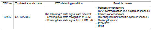
DTC DETECTION LOGIC
NOTE
:
• If DTC B2612 is displayed with DTC U1000, first perform the trouble diagnosis
for DTC U1000. Refer to
BCS-83, "DTC Logic".
• If DTC B2612 is displayed with DTC U1010, first perform the trouble diagnosis for DTC U1010. Refer to BCS-84, "DTC Logic".
DTC CONFIRMATION PROCEDURE
1.PERFORM DTC CONFIRMATION PROCEDURE 1
1. Press push-button ignition switch under the following conditions and wait 1 second or more.
- Selector lever: In the P position - Brake pedal: Not depressed 2. Check DTC in “Self Diagnostic Result” mode of “BCM” using CONSULT-III.
Is DTC detected? YES >> Go to SEC-102, "Diagnosis Procedure".
NO >> GO TO 2.
2.PERFORM DTC CONFIRMATION PROCEDURE 2
1. Turn ignition switch ON.
2. Turn ignition switch OFF.
3. Press driver side door switch and wait 1 second or more.
4. Check DTC in “Self Diagnostic Result” mode of “BCM” using CONSULT-III.
Is DTC detected? YES >> Go to SEC-102, "Diagnosis Procedure".
NO >> INSPECTION END
Diagnosis Procedure
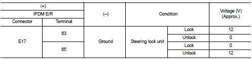
1.CHECK IPDM E/R INPUT SIGNAL
1. Turn ignition switch OFF.
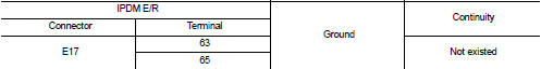
2. Check voltage between IPDM E/R harness connector and ground.
NOTE:
Is the inspection result normal? YES >> GO TO 4.
NO >> GO TO 2.
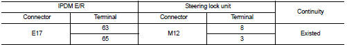
2.CHECK IPDM E/R INPUT SIGNAL CIRCUIT
1. Disconnect IPDM E/R connector and steering lock unit connector.
2. Check continuity between IPDM E/R harness connector and steering lock unit harness connector.
3. Check continuity between IPDM E/R harness connector and ground.
Is the inspection result normal? YES >> GO TO 3.
NO >> Repair or replace harness.
3.REPLACE STEERING LOCK UNIT
1. Replace steering lock unit.
2. Perform the service procedure for steering lock unit replacement. Refer to CONSULT-III Operation Manual NATS-IVIS/NVIS.
>> INSPECTION END
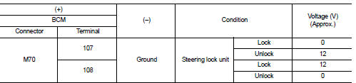
4.CHECK BCM INPUT SIGNAL
1. Turn ignition switch OFF.
2. Check voltage between BCM harness connector and ground.
NOTE:

Is the inspection result normal? YES >> GO TO 5.
NO >> GO TO 6.
5.REPLACE BCM
1. Replace BCM. Refer to BCS-93, "Removal and Installation".
2. Perform initialization of BCM and registration of all Intelligent Keys using CONSULT-III.
For initialization and registration procedures, refer to CONSULT-III Operation Manual NATS-IVIS/NVIS.
>> INSPECTION END
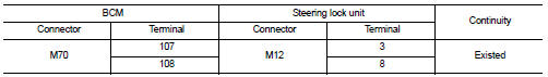
6.CHECK BCM INPUT SIGNAL CIRCUIT
1. Disconnect BCM connector and steering lock unit connector.
2. Check continuity between BCM harness connector and steering lock unit harness connector.
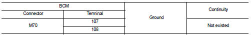
3. Check continuity between BCM harness connector and ground.
Is the inspection result normal? YES >> GO TO 7.
NO >> Repair or replace harness.
7.REPLACE STEERING LOCK UNIT
1. Replace steering lock unit.
2. Perform the service procedure for steering lock unit replacement. Refer to CONSULT-III Operation Manual NATS-IVIS/NVIS.
>> INSPECTION END
 B260F Engine status
Description
BCM receives the engine status signal from ECM via CAN communication.
DTC Logic
DTC DETECTION LOGIC
NOTE:
• If DTC B260F is displayed with DTC U1000, first perform the trouble diagnos ...
 B2619 BCM
DTC Logic
DTC DETECTION LOGIC
DTC CONFIRMATION PROCEDURE
1.PERFORM DTC CONFIRMATION PROCEDURE
1. Press push-button ignition switch under the following conditions and wait
1 second or more.
- ...
Other materials:
System
4WD system : System Diagram
INPUT/OUTPUT SIGNAL
It transmits/receives each signal from the following 4WD control module via
CAN communication line.
4WD system : System Description
• 4WD mode is selectable among 2WD, 4WD-V, and 4WD by operating the 4WD mode
switch.
• When judging drivi ...
Cockpit
1. Outside mirror remote control switch
2. Headlight, fog light and turn signal switch
— Headlight
— Turn signal light
— Fog light
3. Steering wheel
— Electric power steering system
— Horn
— Driver’s supplemental air bag
4. Wiper and washer switch
5. Shift lever
— Continuously Variable ...
Exploded View
1. Mounting rubber
2. Main muffler
3. Seal bearing
4. Spring
5. Mounting rubber
6. Seal bearing
7. Exhaust front tube
8. Heated oxygen sensor 2
9. Sub muffler
10. Gasket
: Always replace after every
disassembly.
: N·m (kg-m, ft-lb)
...
