Nissan Juke Service and Repair Manual : B2198 nats antenna AMP.
DTC Logic
DTC DETECTION LOGIC
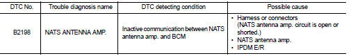
DTC CONFIRMATION PROCEDURE
1.PERFORM DTC CONFIRMATION PROCEDURE 1
1. Contact Intelligent Key backside to push-button ignition switch.
2. Check DTC in “Self Diagnostic Result” mode of “BCM” using CONSULT-III.
Is DTC detected? YES >> Go to SEC-65, "Diagnosis Procedure".
NO >> GO TO 2.
2.PERFORM DTC CONFIRMATION PROCEDURE 2
1. Press the push-button ignition switch.
2. Check DTC in “Self Diagnostic Result” mode of “BCM” using CONSULT-III.
Is DTC detected? YES >> Go to SEC-65, "Diagnosis Procedure".
NO >> INSPECTION END
Diagnosis Procedure
1.CHECK FUSE
1. Turn ignition switch OFF.
2. Check that the following fuse in IPDM E/R is not blown.

Is the fuse fusing? YES >> Replace the blown fuse after repairing the cause of blowing.
NO >> GO TO 2.
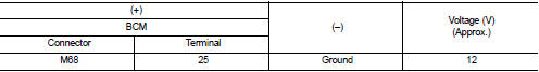
2.CHECK NATS ANTENNA AMP. POWER SUPPLY
1. Disconnect NATS antenna amp. connector.
2. Check voltage between NATS antenna amp. harness connector and ground.
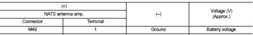
Is the inspection result normal? YES >> GO TO 4.
NO >> GO TO 3.
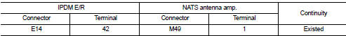
3.CHECK NATS ANTENNA AMP. POWER SUPPLY CIRCUIT
1. Disconnect IPDM E/R connector.
2. Check continuity between IPDM E/R harness connector and NATS antenna amp. connector.
3. Check continuity between IPDM E/R harness connector and ground.
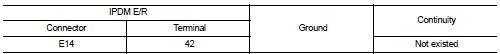
Is the inspection result normal? YES >> Replace IPDM E/R. Refer to PCS-34, "Removal and Installation".
NO >> Repair or replace harness.
4.CHECK NATS ANTENNA AMP. OUTPUT SIGNAL 1
1. Connect NATS antenna amp. connector.
2. Disconnect BCM connector.
3. Check voltage between BCM harness connector and ground.
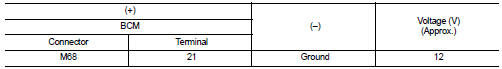
Is the inspection result normal? YES >> GO TO 6.
NO >> GO TO 5.
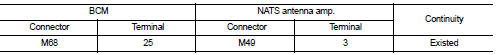
5.CHECK NATS ANTENNA AMP. OUTPUT SIGNAL CIRCUIT 1
1. Disconnect NATS antenna amp. connector.
2. Check continuity between BCM harness connector and NATS antenna amp. connector.
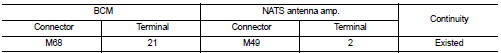
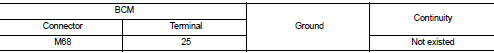
3. Check continuity between BCM harness connector and ground.
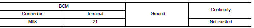
Is the inspection result normal? YES >> Replace NATS antenna amp. Refer to SEC-167, "Removal and Installation".
NO >> Repair or replace harness.
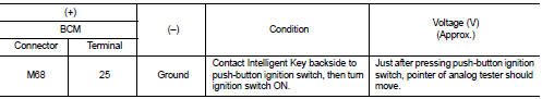
6.CHECK NATS ANTENNA AMP. COMMUNICATION SIGNAL 1
1. Connect BCM connector.
2. Check voltage between BCM harness connector and ground using analog tester.
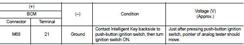
Is the inspection result normal?
YES >> GO TO 7.
NO >> Replace NATS antenna amp. Refer to SEC-167, "Removal and Installation".
7.CHECK NATS ANTENNA AMP. OUTPUT SIGNAL 2
1. Disconnect BCM connector.
2. Check voltage between BCM harness connector and ground.
Is the inspection result normal? YES >> GO TO 9.
NO >> GO TO 8.
8.CHECK NATS ANTENNA AMP. OUTPUT SIGNAL CIRCUIT 2
1. Disconnect NATS antenna amp. connector.
2. Check continuity between BCM harness connector and NATS antenna amp. connector.
3. Check continuity between BCM harness connector and ground.
Is the inspection result normal? YES >> Replace NATS antenna amp. Refer to SEC-167, "Removal and Installation".
NO >> Repair or replace harness.
9.CHECK NATS ANTENNA AMP. COMMUNICATION SIGNAL 2
1. Connect BCM connector.
2. Check voltage between BCM harness connector and ground using analog tester
Is the inspection result normal? YES >> GO TO 10.
NO >> Replace NATS antenna amp. Refer to SEC-167, "Removal and Installation".
10.CHECK NATS ANTENNA AMP. GROUND CIRCUIT
1. Disconnect NATS antenna amp. connector.
2. Check continuity between NATS antenna amp. harness connector and ground.
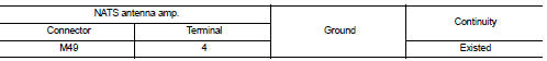
Is the inspection result normal?
YES >> GO TO 11.
NO >> Repair or replace harness.
11.CHECK INTERMITTENT INCIDENT
Refer to GI-42, "Intermittent Incident".
>> INSPECTION END
 B2196 dongle unit
Description
BCM performs ID verification between BCM and dongle unit.
When verification result is OK, BCM permits cranking.
DTC Logic
DTC DETECTION LOGIC
DTC CONFIRMATION PROCEDURE
1.PERFORM ...
 B2013 steering lock unit
DTC Logic
DTC DETECTION LOGIC
DTC CONFIRMATION PROCEDURE
1.PERFORM DTC CONFIRMATION PROCEDURE
1. Lock the steering.
NOTE:
3. Press the push-button ignition switch.
4. Check DTC in “Self D ...
Other materials:
Radiator core supporT
HR16DE
HR16DE : Exploded View
1. Radiator core support upper
2. Air guide RH (MT models)
3. Radiator core support lower
4. Air guide LH
5. Air guide (upper)
6. Air guide LH (CVT models)
7. Air guide RH (CVT models)
: N·m (kg-m, ft-lb)
HR16DE : Removal and Installation
RADIATOR CORE ...
P173A 2GR incorrect ratio
DTC Logic
DTC DETECTION LOGIC
DTC COFIRMATION PROCEDURE
CAUTION:
• Be sure to perform "TM-444, "Diagnosis Procedure"" and then perform "DTC
CONFIRMATION PROCEDURE".
• Never perform "TC CONFIRMATION PROCEDURE" before the repairs. Doing so may
result ...
B2630, B2631 sunload sensor
DTC Logic
DTC DETECTION LOGIC
NOTE:
• If DTC is displayed along with DTC U1000, first perform the trouble diagnosis
for DTC U1000. Refer to HAC-
141, "DTC Logic".
• If DTC is displayed along with DTC U1010, first perform the trouble diagnosis
for DTC U1010. HAC-142,
"DTC L ...
