Nissan Juke Service and Repair Manual : B210C starter control relay
DTC Logic
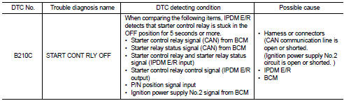
DTC DETECTION LOGIC
NOTE
:
• If DTC B210C is displayed with DTC U1000, first perform the trouble diagnosis
for DTC U1000. Refer to
PCS-30, "DTC Logic".
• When IPDM E/R power supply voltage is low (Approx. 7 - 8 V for about 1 second), the DTC B210C may be detected.
DTC CONFIRMATION PROCEDURE
1.PERFORM DTC CONFIRMATION PROCEDURE
1. Press push-button ignition switch under the following conditions to start engine, and wait 5 seconds or more.
- Selector lever: In the P position - Brake pedal: Depressed 2. Check DTC in “Self Diagnostic Result” mode of “IPDM E/R” using CONSULT-III.
Is DTC detected? YES >> Go to SEC-144, "Diagnosis Procedure".
NO >> GO TO 2.
2.PERFORM DTC CONFIRMATION PROCEDURE 2
1. Stop engine.
2. Perform DTC CONFIRMATION PROCEDURE for DTC P1650. Refer to EC-366, "DTC Logic" (MR16DDT) or EC-725, "DTC Logic" (HR16DE).
3. Turn ignition switch ON.
4. Check DTC in “Self Diagnostic Result” mode of “IPDM E/R” using CONSULT-III.
Is DTC detected? YES >> Refer to SEC-144, "Diagnosis Procedure".
NO >> INSPECTION END
Diagnosis Procedure
1.INSPECTION START
Perform inspection in accordance with procedure that confirms DTC.
Which procedure confirms DTC? DTC confirmation procedure 1>>GO TO 2.
DTC confirmation procedure 2>>GO TO 4.
2.CHECK DTC OF BCM
Check DTC in “Self Diagnostic Result” mode of “BCM” using CONSULT-III.
Is DTC detected? YES >> Perform the trouble diagnosis related to the detected DTC. Refer to BCS-67, "DTC Index".
NO >> GO TO 3.
3.INSPECTION START
1. Turn ignition switch ON.
2. Select “Self Diagnostic Result” mode of “IPDM E/R” using CONSULT-III.
3. Touch “ERASE”.
4. Perform DTC CONFIRMATION PROCEDURE for DTC B210C. Refer to SEC-144, "DTC Logic".
Is DTC detected? YES >> GO TO 6.
NO >> INSPECTION END
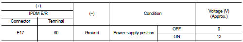
4.CHECK IGNITION POWER SUPLLY NO.2 SIGNAL
1. Turn ignition switch OFF.
2. Disconnect IPDM E/R connector.
3. Check voltage between IPDM E/R harness connector and ground.
Is the inspection result normal? YES >> Replace IPDM E/R. Refer to PCS-34, "Removal and Installation".
NO >> GO TO 5.
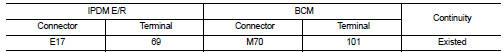
5.CHECK BCM INPUT SIGNAL CIRCUIT
1. Disconnect BCM connector.
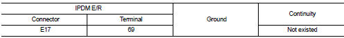
2. Check continuity between IPDM E/R harness connector and BCM harness connector.
3. Check continuity between transmission range switch harness connector and ground.
Is the inspection result normal? YES >> GO TO 6.
NO >> Repair or replace harness.
6.REPLACE BCM
1. Replace BCM. Refer to BCS-93, "Removal and Installation".
2. Perform DTC CONFIRMATION PROCEDURE for DTC B210C. Refer to SEC-144, "DTC Logic".
Is the inspection result normal? YES >> INSPECTION END
NO >> Replace IPDM E/R. Refer to PCS-34, "Removal and Installation".
 B210B starter control relay
DTC Logic
DTC DETECTION LOGIC
NOTE:
If DTC B210B is displayed with DTC U1000, first perform the trouble diagnosis
for DTC U1000. Refer to PCS-
30, "DTC Logic".
DTC CONFIRMATION PROC ...
 B210D starter relay
DTC Logic
DTC DETECTION LOGIC
NOTE:
If DTC B210D is displayed with DTC U1000, first perform the trouble diagnosis
for DTC U1000. Refer to PCS-
30, "DTC Logic".
DTC CONFIRMATION PROC ...
Other materials:
Brake fluid level switch
Component Function Check
1.CHECK BRAKE FLUID LEVEL SWITCH OPERATION
When the brake fluid is full or empty. Then check that the brake warning lamp
in the combination meter turns
ON/OFF correctly.
Is the inspection result normal?
YES >> INSPECTION END
NO >> Proceed to BRC-72, &qu ...
Unbalance steering wheel turning force (torque variation)
Description
Unbalance steering wheel turning force (torque variation).
Diagnosis Procedure
1.CHECK THE ILLUMINATION OF THE EPS WARNING LAMP
Check the EPS warning lamp while engine is running.
Does the EPS warning lamp turn OFF?
YES >> GO TO 2.
NO >> Refer to STC-28, "Diag ...
P0420 three way catalyst function
DTC Logic
DTC DETECTION LOGIC
The ECM monitors the switching frequency ratio of air fuel ratio (A/F)
sensor 1 and heated oxygen sensor 2.
A three way catalyst (manifold) with high oxygen storage capacity
will indicate a low switching frequency of heated oxygen sensor 2.
As oxygen storage c ...
