Nissan Juke Service and Repair Manual : A/C switch
Component Function Check
1.CHECK A/C ON SIGNAL
 With CONSULT-III
1. Turn ignition switch ON.
2. Select “AIR CONDITIONER” of “BCM” using CONSULT-III.
3. Select “AIR COND SW” in “DATA MONITOR” mode, and check status under the following condition.
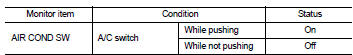
Is the inspection result normal? YES >> INSPECTION END
NO >> Refer to HAC-281, "Diagnosis Procedure".
Diagnosis Procedure
1.CHECK A/C SWITCH POWER SUPPLY
1. Turn ignition switch OFF.
2. Disconnect A/C control connector.
3. Turn ignition switch ON.
4. Check output waveform between A/C control harness connector and ground with using oscilloscope.
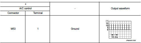
Is the inspection result normal? YES >> GO TO 2.
NO >> GO TO 3.
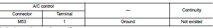
2.CHECK A/C SWITCH GROUND CIRCUIT FOR OPEN
1. Turn ignition switch OFF.
2. Disconnect BCM connector.
3. Check continuity between A/C control harness connector and ground.
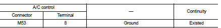
Is the inspection result normal? YES >> Replace A/C control. Refer to HAC-239, "Removal and Installation".
NO >> Repair harness or connector.
3.CHECK A/C SWITCH POWER SUPPLY CIRCUIT FOR OPEN
1. Turn ignition switch OFF.
2. Disconnect BCM connector.
3. Check continuity between A/C control harness connector and BCM harness connector.
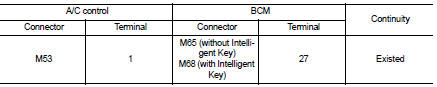
Is the inspection result normal? YES >> GO TO 4.
NO >> Repair harness or connector.
4.CHECK A/C SWITCH POWER SUPPLY CIRCUIT FOR SHORT
Check continuity between A/C control harness connector and ground.
Is the inspection result normal? YES >> Replace BCM. Refer to BCS-93, "Removal and Installation" (with Intelligent Key) or BCS-161, "Removal and Installation" (without Intelligent Key).
NO >> Repair harness or connector.
 Power supply and ground circuit
PTC HEATER CONTROL UNIT : Diagnosis Procedure
1.CHECK FUSE
1. Turn ignition switch OFF.
2. Check 10A fuses (No. 3 and 7).
NOTE:
Refer to PG-23, "Fuse and Fusible Link Arrangement".
...
 Blower fan on signal
Component Function Check
1.CHECK BLOWER FAN ON SIGNAL
With CONSULT-III
1. Turn ignition switch ON.
2. Select “AIR CONDITIONER” of “BCM” using CONSULT-III.
3. Select “FAN ON SIG” in “DATA MONITOR” ...
Other materials:
Cylinder head
Exploded View
REMOVAL
1. Cylinder head assembly
2. Cylinder head bolt
3. Washer
4. Cylinder head gasket
A.Tightening must be done following the installation procedure.
Refer to EM-209
: Always replace after every
disassembly.
: N·m (kg-m, ft-lb)
: Should be lubricated with oil.
D ...
Precaution for Diesel Equipment
CLEANLINESS
CLEANLINESS INSTRUCTIONS WHICH MUST BE FOLLOWED WHEN WORKING ON THE HIGH
PRESSURE
DIRECT INJECTION SYSTEM
Risks relating to contamination
The system is very sensitive to contamination. The risks caused by the
introduction of contamination are:
• Damage or destruction of the high ...
Brake fluid
Inspection
BRAKE FLUID LEVEL
• Check that the fluid level in the reservoir tank is within the specified
range (MAX – MIN lines).
• Visually check for any brake fluid leakage around the reservoir
tank.
• Check the brake system for any leakage if the fluid level is
extremely low (lower than MIN ...
