Nissan Juke Service and Repair Manual : Cylinder head
Exploded View
REMOVAL
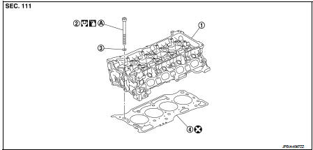
1. Cylinder head assembly
2. Cylinder head bolt
3. Washer
4. Cylinder head gasket
A.Tightening must be done following the installation procedure.
Refer to EM-209
 : Always replace after every
disassembly.
 : N·m (kg-m, ft-lb)
 : Should be lubricated with oil.
DISASSEMBLY
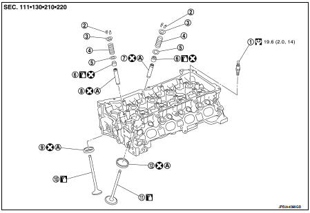
1. Spark plug
2. Valve collet
3. Valve spring retainer
4. Valve spring
5. Valve spring seat
6. Valve oil seal
7. Valve guide (INT)
8. Valve guide (EXH)
9. Valve seat (EXH)
10. Valve (EXH)
11. Valve (INT)
12. Valve seat (INT)
A.Replacement must be following the disassembly and assembly procedure.
Refer to EM-211
: Always replace after every
disassembly.
: N·m (kg-m, ft-lb)
: Should be lubricated with oil.
Removal and Installation
REMOVAL
1. Release fuel pressure. Refer to EC-551, "Work Procedure".
2. Drain engine coolant and engine oil. Refer to CO-11, "Draining" and LU-26, "Draining".
CAUTION:
Perform this step when the engine is cold.
3. Remove the following components and related parts.
• Front road wheel and tire (RH): Refer to WT-7, "Exploded View".
• Fillet mold: Refer to EXT-26, "Exploded View" • Front fender protector (RH): Refer to EXT-22, "Exploded View".
• Drive belt: Refer to EM-155, "Removal and Installation".
• Air duct: Refer to EM-161, "Exploded View".
• Intake manifold: Refer to EM-163, "Exploded View".
• Fuel tube and fuel injector: Refer to EM-173, "Exploded View".
• Water outlet: Refer to CO-26, "Exploded View".
• Exhaust manifold: Refer to EM-166, "Exploded View".
• Rocker cover: Refer to EM-178, "Exploded View".
• Front cover and timing chain: Refer to EM-181, "Exploded View".
• Camshaft: Refer to EM-191, "Exploded View".
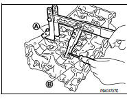
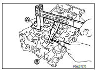
4. Remove cylinder head loosening bolts in reverse order as shown in the figure with cylinder head wrench (commercial service tool).
A : EXH side
B : INT side
 : Engine front
5. Remove cylinder head gasket.
INSTALLATION
1. Install new cylinder head gasket.
2. Tighten cylinder head bolts in numerical order as shown in the figure with the following procedure to install cylinder head.
A : EXH side
B : INT side
 : Engine front
CAUTION: If cylinder head bolts are reused, check their outer diameters before installation. Refer to "Cylinder Head Bolts Outer Diameter".
a. Apply new engine oil to threads and seating surfaces of mounting bolts.
b. Tighten all bolts.
 : 40.0 N·m (4.1 kg-m, 30 ft-lb)
c. Turn all bolts 60 degrees clockwise (angle tightening).
CAUTION:
Check and confirm the tightening angle by using the angle
wrench [SST: KV10112100] (A) or protractor. Avoid judgment
by visual inspection without the tool.
d. Completely loosen.
 : 0 N·m (0 kg-m, 0 ft-lb)
CAUTION:
In this step, loosen bolts in reverse order of that indicated in the figure.
e. Tighten all bolts.
: 40.0 N·m (4.1 kg-m, 30 ft-lb)
f. Turn all bolts 75 degrees clockwise (angle tightening).
g. Turn all bolts 75 degrees clockwise again (angle tightening).
3. Install in the reverse order of removal after this step.
Disassembly and Assembly
DISASSEMBLY
1. Remove spark plug with a spark plug wrench (commercial service tool).
2. Remove valve lifter.
• Identify installation positions, and store them without mixing them up.
3. Remove valve collet.
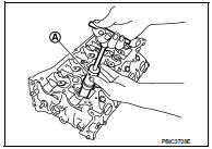
• Compress valve spring with the valve spring compressor, the attachment and the adapter [SST: KV10116200] (A). Remove valve collet with a magnet hand (B).
CAUTION:
When working, be careful not to damage valve lifter holes.
4. Remove valve spring retainer and valve spring.
5. Push valve stem to combustion chamber side, and remove valve.
• Identify installation positions, and store them without mixing them up.
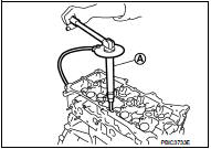
6. Remove valve oil seal with the valve oil seal puller [SST: KV10107902] (A).
7. Remove valve spring seat.
8. When valve seat must be replaced, refer to EM-212, "Inspection" to removal.
9. When valve guide must be replaced, refer to EM-212, "Inspection" to removal.
ASSEMBLY
1. Install valve guide if removed. Refer to EM-212, "Inspection".
2. Install valve seat if removed. Refer to EM-212, "Inspection".
3. Install valve oil seal.
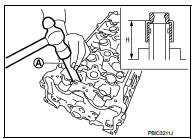
• Install with the valve oil seal drift [SST: KV10115600] (A) to match dimension in the figure.
Height “H” : 13.2 - 13.8 mm (0.519 - 0.543 in)
4. Install valve spring seat.
5. Install valve.
• Install larger diameter to intake side.
6. Install valve spring.
NOTE
:
It can be installed in either direction.
7. Install valve spring retainer.
8. Install valve collet.
• Compress valve spring with the valve spring compressor, the attachment and the adapter [SST: KV10116200] (A). Install valve collet with a magnet hand (B).
CAUTION:
When working, be careful not to damage valve lifter holes
.
• Tap valve stem edge lightly with a plastic hammer after installation to check its installed condition.
9. Install valve lifter.
10. Install spark plug with a spark plug wrench (commercial service tool).
Inspection
INSPECTION AFTER REMOVAL
Cylinder Head Bolts Outer Diameter • Cylinder head bolts are tightened by plastic zone tightening method. Whenever the size difference between “d1” and “d2” exceeds the limit, replace them with a new one.
Limit (“d1”–“d2”): 0.15 mm (0.0059 in)
• If reduction of outer diameter appears in a position other than “d2”, use it as “d2” point.
Cylinder Head Distortion NOTE
:
When performing this inspection, cylinder block distortion should be also
checking. Refer to EM-236, "Inspection".
1. Wipe off engine oil and remove water scale (like deposit), gasket, sealant, carbon, etc. with a scraper.
CAUTION:
Use utmost care not to allow gasket debris to enter passages for engine oil or
engine coolant.
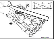
2. At each of several locations on bottom surface of cylinder head, measure the distortion in six directions.
A : Straightedge
B : Feeler gauge
Limit : Refer to EM-253, "Cylinder head".
• If it exceeds the limit, replace cylinder head.
INSPECTION AFTER DISASSEMBLY
VALVE DIMENSIONS
• Check the dimensions of each valve. For the dimensions, refer to EM-253, "Cylinder head".
• If dimensions are out of the standard, replace valve and check valve seat contact. Refer to “VALVE SEAT CONTACT”.
VALVE GUIDE CLEARANCE
Valve Stem Diameter
• Measure the diameter of valve stem with micrometer (A).
Standard : Refer to EM-253, "Cylinder head".
Valve Guide Inner Diameter • Measure the inner diameter of valve guide with bore gauge.
Standard : Refer to EM-253, "Cylinder head".
Valve Guide Clearance • (Valve guide clearance) = (Valve guide inner diameter) – (Valve stem diameter)
Standard and Limit : Refer to EM-253, "Cylinder head".
• If the calculated value exceeds the limit, replace valve and/or valve guide. When valve guide must be replaced. Refer to EM-211, "Disassembly and Assembly".
VALVE SEAT CONTACT
• After confirming that the dimensions of valve guides and valves are within the specifications, perform this procedure.
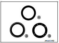
• Apply prussian blue (or white lead) onto contacting surface of valve seat to check the condition of the valve contact on the surface.
• Check if the contact area band is continuous all around the circumference.
A : OK
• If not, grind to adjust valve fitting and check again. If the contacting surface still has “NG” conditions (B) even after the recheck, replace valve seat. Refer to EM-211, "Disassembly and Assembly".
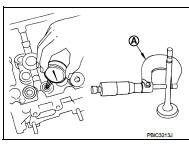
VALVE SPRING SQUARENESS
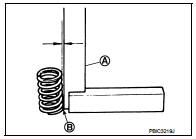
• Set a try square (A) along the side of valve spring and rotate spring. Measure the maximum clearance between the top of spring and try square.
B : Contact
Limit : Refer to EM-253, "Cylinder head".
• If it exceeds the limit, replace valve spring.
VALVE SPRING DIMENSIONS AND VALVE SPRING PRESSURE LO
• Check valve spring pressure with valve spring seat installed at the specified spring height.
CAUTION:
Never remove valve spring seat from valve spring.
Standard : Refer to EM-253, "Cylinder head".
• If the installation load or load with valve open is out of the standard, replace valve spring (with valve spring seat).
INSPECTION AFTER INSTALLATION
Inspection for Leaks
The following are procedures for checking fluids leak, lubricates leak and
exhaust gases leak.
• Before starting engine, check oil/fluid levels including engine coolant and engine oil. If less than required quantity, fill to the specified level. Refer to MA-13, "Fluids and Lubricants".
• Use procedure below to check for fuel leakage.
- Turn ignition switch ON (with engine stopped). With fuel pressure applied to fuel piping, check for fuel leakage at connection points.
- Start engine. With engine speed increased, check again for fuel leakage at connection points.
• Run engine to check for unusual noise and vibration.
NOTE
:
If hydraulic pressure inside timing chain tensioner drops after
removal/installation, slack in the guide may
generate a pounding noise during and just after engine start. However, this is
normal. Noise will stop after
hydraulic pressure rises.
• Warm up engine thoroughly to check there is no leakage of fuel, exhaust gases, or any oil/fluids including engine oil and engine coolant.
• Bleed air from lines and hoses of applicable lines, such as in cooling system.
• After cooling down engine, again check oil/fluid levels including engine oil and engine coolant. Refill to the specified level, if necessary.
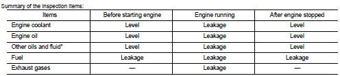
*: Transmission/transaxle fluid, power steering fluid, brake fluid, etc.
 Oil seal
Valve oil seal
VALVE OIL SEAL : Removal and Installation
REMOVAL
1. Remove camshafts. Refer to EM-191, "Exploded View".
2. Remove valve lifters. Refer to EM-191, "Exploded View" ...
 Unit removal and installation
Engine assembly
Exploded View
1. Engine mounting assembly (RH)
2. Rear engine mounting bracket
3. Rear torque rod
4. Engine mounting bracket (LH)
5. Stud bolt
6. Engine mounting bracket ...
Other materials:
Refilling
1. Remove filler plug (1) and gasket. Then fill oil up to mounting
hole for the filler plug.
: Vehicle front
Oil and viscosity : Refer to MA-13, "Fluids
and Lubricants".
Oil capacity : Refer to DLN-117, "General
Specifications".
CAUTION:
Carefully fill the oil. (Fill up ...
Steering switch signal A circuit
Description
Transmits the steering switch signal to NAVI control unit.
Diagnosis Procedure
1.CHECK STEERING SWITCH SIGNAL A CIRCUIT
1. Disconnect NAVI control unit connector and spiral cable connector.
2. Check continuity between NAVI control unit harness connector and spiral cable
harness co ...
Parking lamp circuit
Without daytime running light system
WITHOUT DAYTIME RUNNING LIGHT SYSTEM : Component Function Check
1.CHECK PARKING LAMP OPERATION
CONSULT-III ACTIVE TEST
1. Select “EXTERNAL LAMPS” of IPDM E/R active test item.
2. With operating the test items, check that the parking lamp is turned ON.
TAIL ...
