Nissan Juke Service and Repair Manual : Wiring diagram
Engine control system
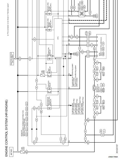
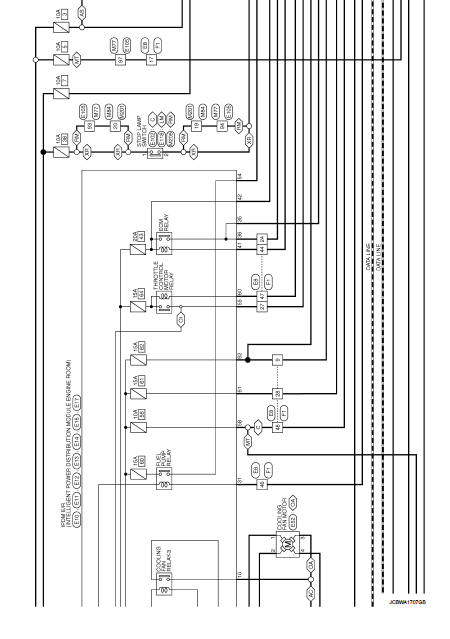
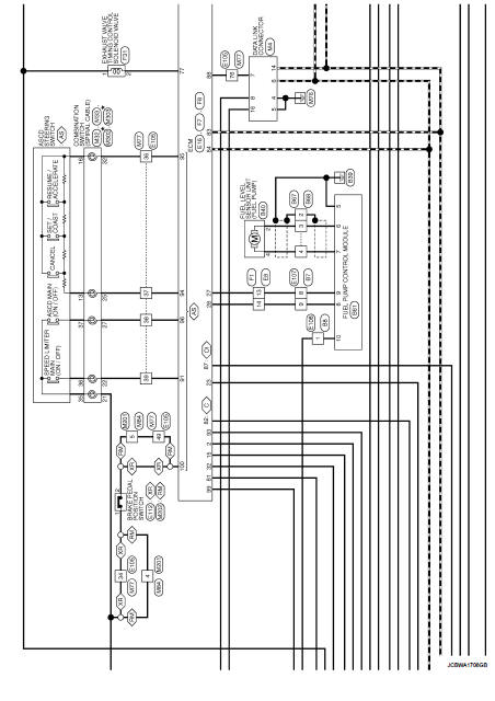
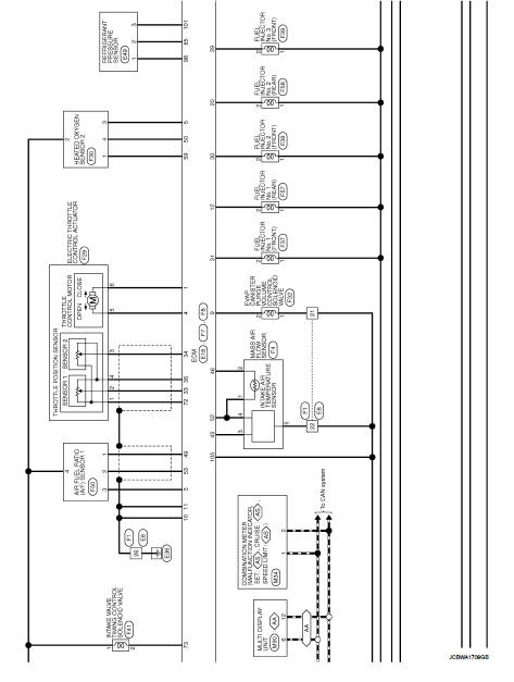
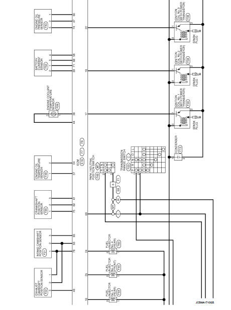
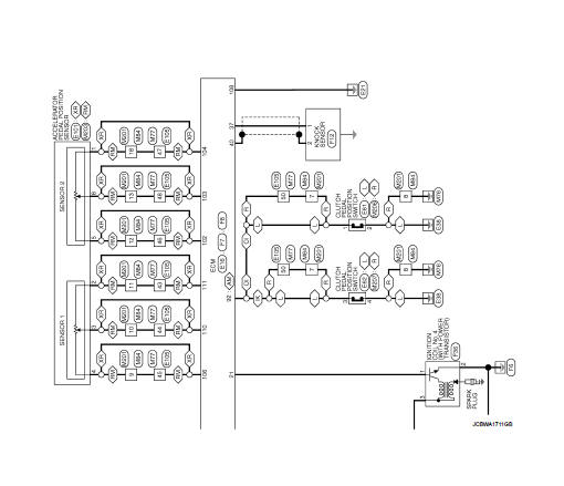
Wiring Diagram
For connector terminal arrangements, harness layouts, and alphabets in a
 (option abbreviation; if not
described in wiring diagram), refer to GI-12, "Connector Information/Explanation
of Option Abbreviation".
 ECU diagnosis information
ECM
Reference Value
VALUES ON THE DIAGNOSIS TOOL
Remarks:
• Specification data are reference values.
• Specification data are output/input values which are detected or supplied by
the ECM at th ...
 Basic inspection
...
Other materials:
Rear oil seal
REAR OIL SEAL : Removal and Installation
REMOVAL
1. Remove transaxle assembly. Refer to TM-301, "Exploded View" (CVT models)
or TM-84, "MR16DDT :
Exploded View" (M/T models).
2. Remove clutch cover and clutch disk (M/T models). Refer to CL-29, "EXCEPT FOR
K9K : Explo ...
Shift P warning lamp
Component Function Check
1.CHECK FUNCTION
1. Select “INTELLIGENT KEY” of “BCM” using CONSULT-III.
2. Select “LCD” in “ACTIVE TEST” mode.
3. Check that the function operates normally according to the following
conditions.
Is the inspection result normal?
YES >> Shift P warning lamp is ...
Blower fan resistor
Exploded View
1. A/C unit assembly
2. Fan control amp.*1
3. Blower fan resistor*2
4. Blower motor
5. Blower motor cover
• *1: Automatic air conditioner
• *2: Manual air conditioner
Removal and Installation
REMOVAL
1. Remove instrument panel assembly. Refer to IP-13, "Removal and ...
