Nissan Juke Service and Repair Manual : Wiring diagram
CHARGING SYSTEM
Wiring Diagram
GASOLINE ENGINE MODELS
For connector terminal arrangements, harness layouts, and alphabets in a
 (option abbreviation; if not
described in wiring diagram), refer to GI-12, "Connector Information/Explanation
of Option Abbreviation".
DIESEL ENGINE MODELS
For connector terminal arrangements, harness layouts, and alphabets in a
 (option abbreviation; if not
described in wiring diagram), refer to GI-12, "Connector Information/Explanation
of Option Abbreviation".
 System
Charging system
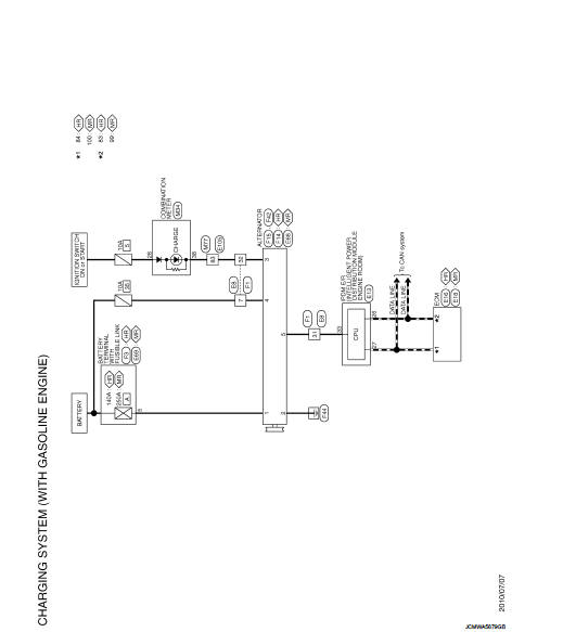
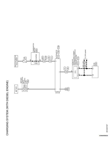
CHARGING SYSTEM : System Diagram
GASOLINE ENGINE MODELS
DIESEL ENGINE MODELS
CHARGING SYSTEM : System Description
The alternator provides DC voltage to operate the vehicle's e ...
 Basic inspection
...
Other materials:
Thermo control amplifier
Removal and Installation
REMOVAL
1. Remove evaporator.
• Refer to HA-55, "EVAPORATOR : Removal and Installation". (HR16DE)
• Refer to HA-115, "EVAPORATOR : Removal and Installation". (MR16DDT)
2. Remove the thermo control amp. from evaporator.
INSTALLATION
Note the fol ...
P0380 glow rela
DTC Logic
DTC DETECTION LOGIC
NOTE:
If DTC P0380 is displayed with DTC P0560 or P0657, first perform trouble
diagnosis for DTC P0560 or P0657.
Refer to EC-963, "DTC Logic" (DTC P0560) or EC-976, "DTC Logic" (DTC P0657).
Diagnosis Procedure
1.CHECK GLOW RELAY POWER SUP ...
Diagnosis and repair work flow
Work Flow
OVERALL SEQUENCE
DETAILED FLOW
1.GET INFORMATION FOR SYMPTOM
1. Get the detailed information from the customer about the symptom (the
condition and the environment
when the incident/malfunction occurred).
2. Check operation condition of the function that is malfunctioning.
> ...
