Nissan Juke Service and Repair Manual : Wiring diagram
CAN SYSTEM
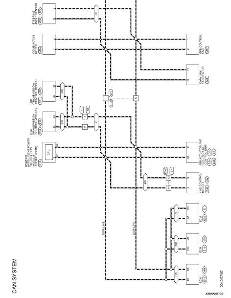
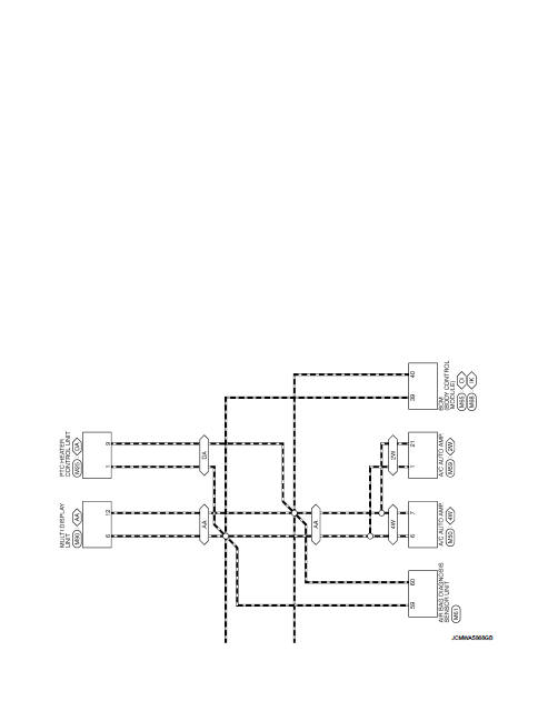
Wiring Diagram
For connector terminal arrangements, harness layouts, and alphabets in a
 (option abbreviation; if not
described in wiring diagram), refer to GI-12, "Connector Information/Explanation
of Option Abbreviation".
 System
Can communication system
CAN COMMUNICATION SYSTEM : System Diagram
CAN COMMUNICATION SYSTEM : System Description
Description
• CAN (Controller Area Network) is a serial communication line for re ...
 Basic inspection
DIAGNOSIS AND REPAIR WORKFLOW
Interview Sheet
NOTE:
Refer to LAN-17, "Trouble Diagnosis Procedure" for how to use interview sheet.
...
Other materials:
C1109 power and ground system
DTC Logic
DTC DETECTION LOGIC
DTC CONFIRMATION PROCEDURE
1.PRECONDITIONING
If “DTC CONFIRMATION PROCEDURE” has been previously conducted, always turn
ignition switch OFF and
wait at least 10 seconds before conducting the next test.
>> GO TO 2.
2.CHECK DTC DETECTION
With CONSULT ...
P1574 ASCD vehicle speed sensor
Description
The ECM receives two vehicle speed sensor signals via CAN communication line.
One is sent from combination
meter, and the other is from TCM (Transmission control module). The ECM uses
these signals for ASCD
control. Refer to EC-64, "AUTOMATIC SPEED CONTROL DEVICE (ASCD) : Sys ...
Bluetooth® Hands-Free Phone System
WARNING
• Use a phone after stopping your vehicle in a safe location. If you have
to use a phone while driving, exercise extreme caution at all times so full attention
may be given to vehicle operation.
• If you find yourself unable to devote full attention to vehicle operation while
talking ...
