Nissan Juke Service and Repair Manual : Wiring diagram
HORN
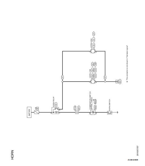
Wiring Diagram
For connector terminal arrangements, harness layouts, and alphabets in a
 (option abbreviation; if not
described in wiring diagram), refer to GI-12, "Connector Information/Explanation
of Option Abbreviation".
 Precaution
Precaution for Supplemental Restraint System (SRS) "AIR BAG" and "SEAT
BELT
PRE-TENSIONER"
The Supplemental Restraint System such as “AIR BAG” and “SEAT BELT
PRE-TENSIONER”, ...
 Removal and installation
HORN
Exploded View
WITHOUT VEHICLE SECURITY SYSTEM
1. Horn high
2. Horn low
3. Horn bracket
WITH VEHICLE SECURITY SYSTEM
1. Horn low
2. Horn bracket
Removal and Installation
REMOVAL
...
Other materials:
Push-button ignition switch
Component Function Check
1.CHECK FUNCTION
1. Select “PUSH SW” in “Data Monitor” mode with CONSULT-III.
2. Check the push-button ignition switch signal under the following conditions.
Is the indication normal?
YES >> INSPECTION END.
NO >> Go to PCS-108, "Diagnosis Procedure&q ...
B2608 starter relay
DTC Logic
DTC DETECTION LOGIC
NOTE:
• If DTC B2608 is displayed with DTC U1000, first perform the trouble diagnosis
for DTC U1000. Refer to
BCS-83, "DTC Logic".
• If DTC B2608 is displayed with DTC U1010, first perform the trouble diagnosis
for DTC U1010. Refer to
BCS-84, "D ...
Diagnosis and repair workflow
Gasoline engine models
GASOLINE ENGINE MODELS : Work Flow
OVERALL SEQUENCE
DETAILED FLOW
1.PRELIMINARY INSPECTION
Perform the preliminary inspection. Refer to CHG-17, "Inspection Procedure".
Models with battery current sensor>>GO TO 2.
Models without battery current sens ...
