Nissan Juke Service and Repair Manual : Wiring diagram
EXTERIOR LIGHTING SYSTEM
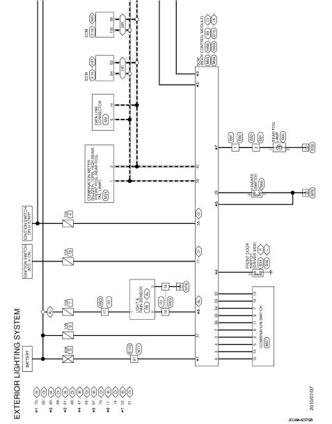
Wiring Diagram
For connector terminal arrangemants, harness layouts, and alphabets in a
 (option abbreviation: if not
described in wiring diagram), refer to GI-12, "Connector Information/Explanation
of Option Abbreviation".
 Ecu diagnosis informatioN
BCM, IPDM E/R
List of ECU Reference
WITH INTELLIGENT KEY
WITHOUT INTELLIGENT KEY
...
 Basic inspection
DIAGNOSIS AND REPAIR WORKFLOW
Work Flow
OVERALL SEQUENCE
DETAILED FLOW
1.INTERVIEW FOR MALFUNCTION
Interview the symptom to the customer.
>> GO TO 2.
2.SYMPTOM CHECK
Check the sympto ...
Other materials:
Charge air cooler
Exploded View
1. Air inlet tube assembly
2. Air inlet tube bracket
3. Clamp
4. Air inlet hose
5. Gasket
6. Turbocharger
7. Mounting rubber
8. Charge air cooler
9. Air inlet tube assembly
10. Air inlet tube bracket
11. Air inlet hose
12. Air inlet tube assembly
13.Turbochager b ...
Compressor
Exploded View
REMOVAL
1. High-pressure flexible hose
2. O-ring
3. Compressor
4. O-ring
5. Low-pressure flexible hose
A. To condenser
B. To evaporator
: N·m (kg-m, ft-lb)
DISASSEMBLY
1. Compressor unit
2. Field coil
3. Snap ring
4. Pulley assembly
5. Snap ring
6. Shim
7. ...
B2623 inside antenna
DTC Logic
DTC DETECTION LOGIC
DTC CONFIRMATION PROCEDURE
1.PERFORM DTC CONFIRMATION PROCEDURE
1. Select “INTELLIGENT KEY” of “BCM” using CONSULT-III.
2. Select “INSIDE ANT DIAGNOSIS” in “WORK SUPPORT” mode.
3. Perform inside key antenna (“INSIDE ANT DIAGNOSIS”) on “WORK SUPPORT” of
“INTELLIG ...
