Nissan Juke Service and Repair Manual : Wiring diagram
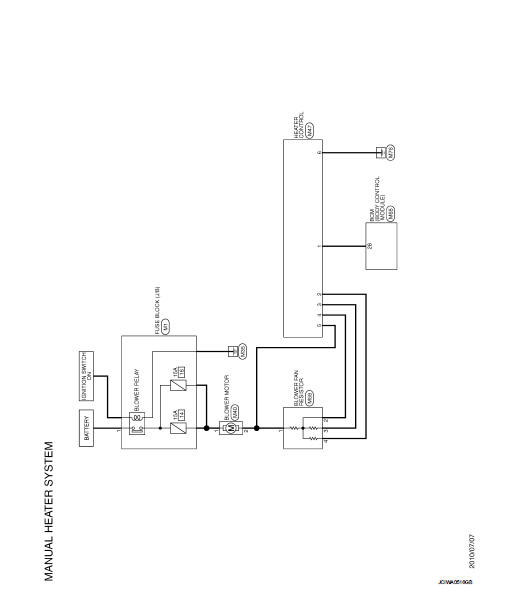
MANUAL HEATER SYSTEM
Wiring Diagram
For connector terminal arrangements, harness layouts, and alphabets in a
 (option abbreviation; if not
described in wiring diagram), refer to GI-12, "Connector Information/Explanation
of Option Abbreviation".
 ECU diagnosis information
BCM
List of ECU Reference
...
 Basic inspection
...
Other materials:
Water outlet
Exploded View
1. Engine coolant temperature sensor
2. O-ring
3. Lock plate
4. Gasket
5. Water outlet and thermostat assembly
6. Air relief plug
7. Clamp
8. Water hose
9. Water pipe
A. To radiator hose upper
B. To EGR cooler hose
C. To heater hose
: N·m (kg-m, ft-lb)
: Always ...
Precaution for Supplemental Restraint System (SRS) "AIR BAG" and "SEAT BELT
PRE-TENSIONER"
The Supplemental Restraint System such as “AIR BAG” and “SEAT BELT PRE-TENSIONER”,
used along
with a front seat belt, helps to reduce the risk or severity of injury to the
driver and front passenger for certain
types of collision. Information necessary to service the system safely is
include ...
Accelerator pedal released position learning
Description
Accelerator Pedal Released Position Learning is a function of ECM to learn
the fully released position of the
accelerator pedal by monitoring the accelerator pedal position sensor output
signal. It must be performed each
time harness connector of accelerator pedal position sensor ...
