Nissan Juke Service and Repair Manual : Wiring diagram
BRAKE CONTROL SYSTEM
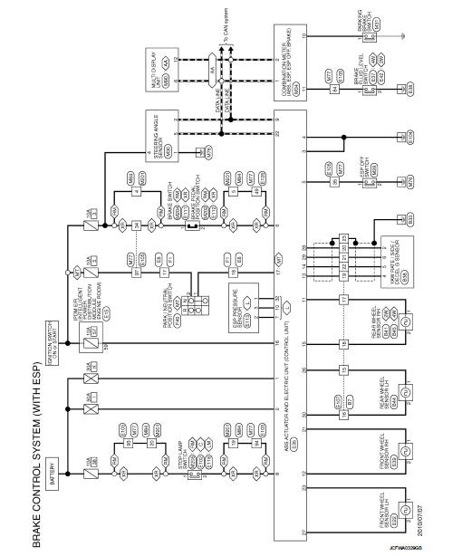
Wiring Diagram
For connector terminal arrangements, harness layout, and alphabets in a
(option abbreviation; if not
described in wiring diagram), refer to GI-12, "Connector Information/Explanation
of Option Abbreviation".
 ECU diagnosis information
ABS actuator and electric unit (control unit)
Reference Value
CONSULT-III DATA MONITOR STANDARD VALUE
*1: Confirm tire pressure is standard value.
*2: Refer to “valve operation” in BRC-105, ...
 Basic inspection
...
Other materials:
B1121 satellite sensor LH
DTC Logic
DTC DETECTION LOGIC
DTC CONFIRMATION PROCEDURE
1.CHECK SELF-DIAG RESULT
With CONSULT-III
1. Turn ignition switch ON.
2. Perform “Self Diagnostic Result” mode of “AIR BAG” using CONSULT-III.
Without CONSULT-III
1. Turn ignition switch ON.
2. Check the air bag warning lamp statu ...
Oil pan (lower)
Exploded View
1. O-ring
2. Oil pan (upper)
3. Oil level gauge guide
4. O-ring
5. Oil level gauge
6. Oil pump drive chain
7. Crankshaft sprocket
8. Oil pump sprocket
9. Oil pump chain tensioner
10. Oil pump
11. Drain plug
12. Drain plug washer
13. Oil pan (lower)
14. Oil fil ...
Camshaft valve clearance
Inspection and Adjustment
INSPECTION
Perform inspection as follows after removal, installation or replacement of
camshaft or valve-related parts, or if
there is unusual engine conditions regarding valve clearance.
1. Remove rocker cover. Refer to EM-53, "Exploded View".
2. Measure ...
