Nissan Juke Service and Repair Manual : Wheel sensor
Front wheel sensor : Exploded View
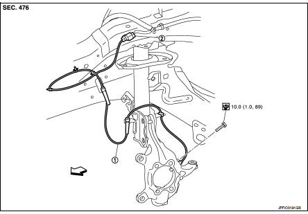
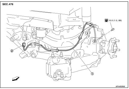
1. Front LH wheel sensor 2. Front LH wheel sensor harness connector
 : Vehicle front
 : N·m (kg-m, in-lb)
NOTE:
Front RH wheel sensor is symmetrically opposite of LH.
Front wheel sensor : Removal and Installation
REMOVAL
1. Remove tires.
2. Remove the fender protector (front). Refer to EXT-22, "Removal and Installation".
3. Remove front wheel sensor from steering knuckle.
CAUTION:
Never rotate and never pull front wheel sensor as much as possible, when pulling
out.
4. Remove front wheel sensor harness from the vehicle.
CAUTION:
Never twist or pull front wheel sensor harness, when removing.
INSTALLATION
Note the following, and install in the reverse order of the removal.
• Check that there is no foreign material like iron powder or damage on inner surface of front wheel sensor mounting hole of steering knuckle and sensor rotor. Install after cleaning when there are foreign material like iron powder, or replace when there is a malfunction.• Check that there is no foreign material like iron powder or damage on inner surface of front wheel sensor mounting hole of steering knuckle and sensor rotor. Install after cleaning when there are foreign material like iron powder, or replace when there is a malfunction.
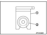
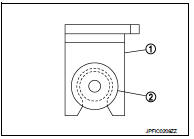
• Never twist front wheel sensor harness when installing front wheel sensor. Check that grommet (2) is fully inserted to bracket (1).
Check that front wheel sensor harness is not twisted after installation.
• Never twist front wheel sensor harness when installing front wheel sensor. Check that grommet (2) is fully inserted to bracket (1).
Check that front wheel sensor harness is not twisted after installation.
Rear wheel sensor : Exploded View
2WD
Left side
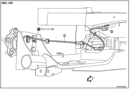
1. Rear LH wheel sensor 2. Rear LH wheel sensor harness connector
: Vehicle front
: N·m (kg-m, in-lb)
Right side
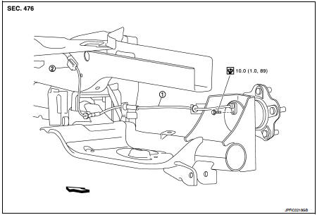
1. Rear RH wheel sensor 2. Rear RH wheel sensor harness connector
: Vehicle front
: N·m (kg-m, in-lb)
4WD
1. Rear LH wheel sensor 2. Rear LH wheel sensor harness connector
: Vehicle front
: N·m (kg-m, in-lb)
NOTE
:
Rear RH wheel sensor is symmetrically opposite of LH.
Rear wheel sensor : Removal and Installation
REMOVAL
1. Remove rear wheel sensor from wheel hub and bearing assembly (2WD).
CAUTION:
Never rotate or pull rear wheel sensor as much as possible, when pulling out.
2. Remove rear wheel sensor from axle housing (4WD).
CAUTION:
Never rotate or pull rear wheel sensor as much as possible, when pulling out.
3. Remove rear wheel sensor harness from the vehicle.
CAUTION:
Never twist and never pull rear wheel sensor harness, when removing.
INSTALLATION
Note the following, and install in the reverse order of the removal.
• Check that there is no foreign material like iron powder or damage on inner surface of rear wheel sensor mounting hole of wheel hub and bearing assembly and sensor rotor. Install after cleaning when there are foreign material like iron powder, or replace when there is a malfunction.
• Never twist rear wheel sensor harness when installing rear wheel sensor. Check that grommet (2) is fully inserted to bracket (1).
Check that rear wheel sensor harness is not twisted after installation.
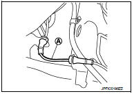
CAUTION:
Check that the identification line (A) of the rear wheel sensor
is faced upward.

 Sensor rotor
Front sensor rotor : Removal and Installatio
REMOVAL
Replace wheel hub as an assembly when replacing because sensor rotor cannot
be disassembled.
• MR16DDT: Refer to FAX-11, "Removal and I ...
Other materials:
Camshaft valve clearance
Inspection and Adjustment
INSPECTION
Perform inspection as follows after removal, installation or replacement of
camshaft or valve-related parts, or if
there is unusual engine conditions regarding valve clearance.
1. Remove rocker cover. Refer to EM-178, "Removal and Installation".
...
LAN System can system (type 7)
DTC/CIRCUIT DIAGNOSIS
Main line between IPDM-E and DLC circuit
Diagnosis Procedure
1.CHECK CONNECTOR
1. Turn the ignition switch OFF.
2. Disconnect the battery cable from the negative terminal.
3. Check the following terminals and connectors for damage, bend and loose
connection (connector s ...
P060A ECM
DTC Logic
DTC DETECTION LOGIC
Diagnosis Procedure
1.INSPECTION START
1. Turn ignition switch ON.
2. Erase DTC.
3. Turn ignition switch OFF and wait for 20 seconds.
4. Turn ignition switch ON and perform the self-diagnosis.
Is the DTC P060A displayed again?
YES >> GO TO 2.
NO &g ...
