Nissan Juke Service and Repair Manual : Wheel alignment
Inspection
DESCRIPTION
Measure wheel alignment under unladen conditions.
NOTE
:
“Unladen conditions” means that fuel, engine coolant, and lubricant are full.
Spare tire, jack, hand tools and
mats are in designated positions.
PRELIMINARY CHECK
Check the following:
• Tires for improper air pressure and wear
• Road wheels for runout: refer to WT-7, "Inspection".
• Wheel bearing axial end play: refer to RAX-12, "Inspection".
• Shock absorber operation • Each mounting point of axle and suspension for looseness and deformation • Each of lower link, upper link, rear suspension member, suspension arm and shock absorber for cracks, deformation, and other damage • Vehicle height (posture)
CAMBER
• Measure camber of both right and left wheels with a suitable alignment gauge.
Camber : Refer to RSU-37, "Wheel Alignment".
• If camber is outside specified range, adjust with adjusting bolt in rear lower link. Refer to RSU-21, "Adjustment".
TOE-IN
Measure toe-in by the following procedure.
WARNING:
• Always perform the following procedure on a flat surface.
• Check that no person is in front of vehicle before pushing it.
1. Bounce the front of vehicle up and down to stabilize the vehicle height (posture).
2. Push vehicle straight ahead about 5 m (16 ft).
3. Put matching mark (A) on base line of the tread (rear side) of both tires at the same height of hub center. These are measuring points.
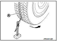
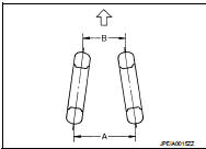
4. Measure distance (A) (rear side).
: Vehicle front
5. Push vehicle slowly ahead to rotate wheels 180 degrees (1/2 turn).
NOTE
:
If the wheels rotates more than 180 degrees (1/2 turn), start this
procedure again from the beginning. Do not push the vehicle
backward.
6. Measure distance (B) (front side).
Total toe-in = A − B Total toe-in : Refer to RSU-37, "Wheel Alignment".
• If toe-in is outside specified range, adjust with adjusting bolt in upper link and lower link. Refer to RSU- 21, "Adjustment".
Adjustment
CAMBER, TOE-IN
CAUTION:
• Adjust camber first, then adjust toe-in last. never change the order.
• If camber angle needs to be adjusted, toe-in adjustment is necessary.
• Minimize difference of left and right toe-in within tolerance
.
1. Loosen mounting nuts of upper link and lower link on the suspension member side.
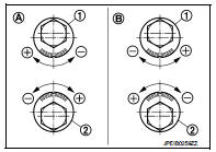
2. Adjust camber and toe-in by turning upper link adjusting bolt (1) and lower link adjusting bolt (2) alternately.
A : Left side
B : Right side
NOTE:
Upper link adjusting bolt Positive direction : Upper link slides into inner side of vehicle.
Negative direction : Upper link slides into outer side of vehicle.
Lower link adjusting bolt Positive direction : Lower link slides into outer side of vehicle.
Negative direction : Lower link slides into inner side of vehicle.
• Refer to the table below for easier adjustment
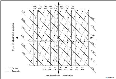
- Obtain the amount of camber and toe-in by calculating the difference between the measurement result and the standard value.
- Obtain the needed adjustment amount from the graph and move adjusting bolts, respectively.
3. After adjustment, tighten mounting nuts of upper link and lower link on the suspension member side.
CAUTION:
When tightening nut to the specified torque, the bolt must be fixed with a
wrench.
 Rear suspension assembly
Inspection
MOUNTING INSPECTION
Check the mounting conditions (looseness, backlash) of each component and
component conditions (wear,
damage) are normal.
SHOCK ABSORBER
Check for oil leakage a ...

Other materials:
Engine stand setting
NOTE:
Explained here is how to disassemble with engine stand supporting transaxle
surface. When using different
type of engine stand, note with difference in steps and etc.
1. Remove the engine and the transaxle assembly from the vehicle, and separate
the transaxle from the
engine. Refer t ...
MR16DDT : Inspection and Adjustment
INSPECTION
Magnetic Switch Check
• Before starting to check, disconnect the battery cable from the negative
terminal.
• Disconnect “M” terminal of starter motor.
1. Continuity test [between “S” terminal (A) and switch body]
B : “B” terminal
C : “M” terminal
• Replace magnetic switch if co ...
Precaution Necessary for Steering Wheel Rotation after Battery Disconnect
NOTE:
• Before removing and installing any control units, first turn the ignition
switch to the LOCK position, then disconnect
both battery cables.
• After finishing work, confirm that all control unit connectors are connected
properly, then re-connect both
battery cables.
• Always use CONS ...
