Nissan Juke Service and Repair Manual : Water pump
Exploded View
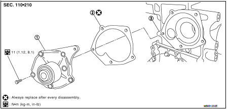
1. Water pump
2. Gasket
3. Cylinder block
Removal and Installation
WARNING:
Never remove the radiator cap when the engine is hot. Serious burns could occur
from high pressure
coolant escaping from the radiator.
REMOVAL
1. Drain engine coolant. Refer to CO-62, "Draining".
CAUTION:
Perform when engine is cold.
2. Remove front wheel RH.
3. Remove fender protector (RH). Refer to EXT-22, "Exploded View" 4. Remove drive belt. Refer to EM-276, "Removal and Installation".
5. Remove timing belt and inner cover. Refer to EM-302, "Exploded View".
6. Remove the water pump.
• Coolant will leak from the cylinder block, so have a receptacle ready below.
CAUTION:
• Handle the water pump vane so that it does not contact any other parts.
• Water pump cannot be disassembled and should be replaced as a unit.
INSTALLATION
• Install in the reverse order of removal.
Inspection
INSPECTION AFTER REMOVAL
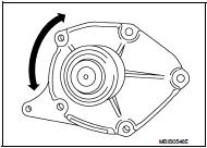
• Visually make sure there is no significant dirt or rusting on the water pump body and vane.
• Make sure there is no looseness in the vane shaft, and that it turns smoothly when rotated by hand.
• If there are any unusualness, replace the water pump assembly.
INSPECTION AFTER INSTALLATION
• Check for engine coolant leaks using reservoir tank cap tester. Refer to CO-62, "Inspection".
 Cooling fan
Exploded View
1. Fan motorCooling fan
2. Fan shroud
3. Cooling fan
A. Reverse screw
: Apply thread locking sealant.
: Vehicle front
: N·m (kg-m, in-lb)
Removal and Installation
REMOVAL
1 ...
 Thermo plunger unit
Exploded View
1. Side member LH
2. Thermo plunger control unit
3. Thermo plunger relay
4. Thermo plunger connector
5. Earth lead
6. Thermo plunger unit
7. Bracket stay
Vehicle front
: ...
Other materials:
Precaution for Supplemental Restraint System (SRS) "AIR BAG" and "SEAT BELT
PRE-TENSIONER"
The Supplemental Restraint System such as “AIR BAG” and “SEAT BELT PRE-TENSIONER”,
used along
with a front seat belt, helps to reduce the risk or severity of injury to the
driver and front passenger for certain
types of collision. Information necessary to service the system safely is
include ...
S terminal circuit
Description
The output voltage of the alternator is controlled by the IC voltage
regulator at the “S” terminal detecting the
input voltage.
The “S” terminal circuit detects the battery voltage to adjust the alternator
output voltage with the IC voltage
regulator.
Diagnosis Procedure
1.CH ...
Diagnosis system (TCM)
CONSULT-III Function (TRANSMISSION)
CONSULT-III can display each diagnostic item using the diagnostic test modes
shown below.
FUNCTION
*: “Function Test” can be selected, but do not use it.
WORK SUPPORT MODE
Display Item List
Engine Brake Adjustment
“ENGINE BRAKE LEVEL”
0: Initial ...
