Nissan Juke Service and Repair Manual : Water outlet
Exploded View
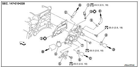
1. Engine coolant temperature sensor
2. Clamp
3. Gasket
4. Clamp
5. Bracket
6. Clamp
7. Water outlet
8. Clamp
9. Clamp
10. Washer
A. To electric throttle control actuator
B. To radiator
C. To CVT oil warmer
D. To heater core
E. To electric throttle control actuator
 : Engine front
 : Always replace after every
disassembly.
 : N·m (kg-m, ft-lb)
Removal and Installation
REMOVAL
1. Drain engine coolant from radiator. Refer to CO-37, "Draining".
CAUTION:
• Perform this step when engine is cold.
2. Remove air duct (inlet) and air ducts. Refer to EM-161, "Removal and Installation".
3. Disconnect radiator hose (upper). Refer to CO-42, "Exploded View".
4. Disconnect harness connector from engine coolant temperature sensor.
5. Remove water hoses and heater hoses.
6. Remove water outlet.
7. Remove engine coolant temperature sensor from water outlet, if necessary.
INSTALLATION
Installation is the reverse order of removal.
Inspection
INSPECTION AFTER REMOVAL
Water Control Valve
• Place a thread (A) so that it is caught in the valves of water control valve (1). Immerse fully in a container (B) filled with water. Heat while stirring.
• The valve opening temperature is the temperature at which the valve opens and falls from the thread.
• Continue heating. Check the continuous valve lifting toward maximum valve lift.
NOTE
:
The maximum valve lift amount standard temperature for water
control valve is the reference value.
• After checking the maximum valve lift amount, lower the water temperature and check the valve closing temperature.
Standard: Refer to CO-54, "Water Control Valve".
• If out of the standard, replace water control valve.
INSPECTION AFTER INSTALLATION
• Check for leakage of engine coolant using the radiator cap tester adapter (commercial service tool) and the radiator cap tester (commercial service tool). Refer to CO-37, "Inspection".
• Start and warm up the engine. Check visually that there is no leakage of engine coolant.
 Thermostat
Exploded View
1. Radiator hose (upper)
2. Water inlet
3. Rubber ring
4. Thermostat
A. To radiator
: Always replace after every
disassembly.
: N·m (kg-m, ft-lb)
Removal and Installation
...

Other materials:
Reverse idler shaft and gear
Exploded View
1. Reverse output gear
2. Snap ring
3. Reverse baulk ring
4. Return spring
5. Needle bearing
6. Seal washer
7. Reverse idler shaft
8. Spacer
9. Reverse input gear
10. Lock washer
11. Spring washer
: Replace the parts as a set.
: Always replace after every
disass ...
Door request switch
Component Function Check
1.CHECK FUNCTION
1. Select “INTELLIGENT KEY” of “BCM” using CONSULT-III.
2. Select “REQ SW-DR”, “REQ SW-AS” in “DATA MONITOR” mode.
3. Check that the function operates normally according to the following
conditions.
Is the inspection result normal?
YES >> Fro ...
Battery terminal with fusible link
Exploded View
1 : Battery terminal with fusible link
2 : Harness connector
: N·m (kg-m, ft-lb)
Removal and Installation
REMOVAL
1. Disconnect the battery cable from the negative terminal.
2. Remove cover of battery positive terminal.
3. Remove harness mounting nut and battery terminal with ...
