Nissan Juke Service and Repair Manual : Valve oil seal
VALVE OIL SEAL : Removal and Installation
REMOVAL
1. Remove camshafts. Refer to EM-78, "Exploded View".
2. Remove valve lifters. Refer to EM-78, "Exploded View".
3. Rotate crankshaft, and set piston whose valve oil seal is to be removed to TDC. This will prevent valve from dropping into cylinder.
CAUTION:
When rotating crankshaft, be careful to avoid scarring front cover with timing
chain.
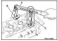
4. Remove valve collet.
• Compress valve spring with the valve spring compressor [SST: KV10116200 (J-26336-A)] (A), the attachment [SST: KV10115900 (J-26336-20)] (C), and the adapter [SST: KV10109220 ( — )] (B). Remove valve collet with magnet hand.
CAUTION:
Be careful not to damage valve lifter holes.
5. Remove valve spring retainer and valve spring (with valve spring seat).
CAUTION:
Never remove valve spring seat from valve spring.
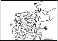
6. Remove valve oil seal with the valve oil seal puller [SST: KV10107902 (J-38959)] (A).
INSTALLATION
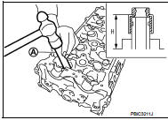
1. Apply new engine oil to valve oil seal joint surface and seal lip.
2. Press in valve oil seal to the height (H) shown in the figure with the valve oil seal drift [SST: KV10115600 (J-38958)] (A).
Height (H) : 15.1 - 15.7 mm (0.594 - 0.618 in)
3. Install in the reverse order of removal, for the rest of parts.
 Oil seal
...
 Front oil seal
FRONT OIL SEAL : Removal and Installation
REMOVAL
1. Remove the following parts.
• Front fender protector (RH): Refer to EXT-22, "Exploded View".
• Drive belt: Refer to EM-20, "Expl ...
Other materials:
CAN communication circuit
Description
CAN (Controller Area Network) is a serial communication line for real time
application. It is an on-vehicle multiplex
communication line with high data communication speed and excellent error
detection ability. Many electronic
control units are equipped onto a vehicle, and each co ...
Precaution for Power Generation Voltage Variable Control System
CAUTION:
For thailand model, the battery current sensor that is installed to the battery
cable at the negative terminal
measures the charging/discharging current of the battery, and performs various
controls. If the
electrical component or the ground wire is connected directly to the battery ...
B1115 satellite sensor RH
DTC Logic
DTC DETECTION LOGIC
DTC CONFIRMATION PROCEDURE
1.CHECK SELF-DIAG RESULT
With CONSULT-III
1. Turn ignition switch ON.
2. Perform “Self Diagnostic Result” mode of “AIR BAG” using CONSULT-III.
Without CONSULT-III
1. Turn ignition switch ON.
2. Check the air bag warning lamp statu ...
