Nissan Juke Service and Repair Manual : Upper link
Exploded View
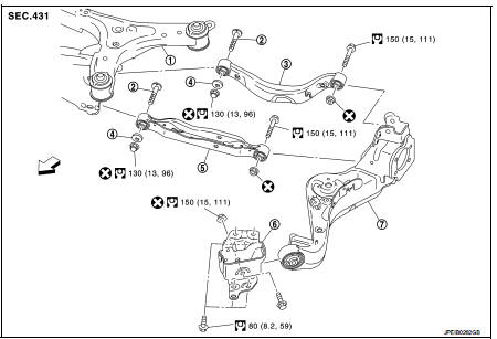
1. Rear suspension member
2. Adjusting bolt
3. Upper link
4. Eccentric disk
5. Lower link
6. Suspension arm bracket
7. Suspension arm
 : Vehicle front
 : Always replace after every
disassembly.
 : N·m (kg-m, ft-lb)
Removal and Installation
REMOVAL
1. Remove tires. WT-7, "Removal and Installation".
2. Remove wheel sensor and sensor harness. Refer to BRC-86, "REAR WHEEL SENSOR : Removal and Installation" (Without ESP), BRC-227, "REAR WHEEL SENSOR : Removal and Installation" (With ESP).
3. Set jack under suspension arm.
CAUTION:
• Never damage the suspension arm with a jack.
• Check the stable condition when using a jack.
4. Remove eccentric disc, adjusting bolt, mounting bolt, and nut, then remove upper link.
5. Perform inspection after removal. Refer to RSU-33, "Inspection".
INSTALLATION
Note the following, and install in the reverse order of removal.
• Perform final tightening of rear suspension member and axle installation position (rubber bushing), under unladen conditions with tires on level ground.
• Never reuse upper link mounting nut.
• Perform inspection after installation. Refer to RSU-33, "Inspection".
Inspection
INSPECTION AFTER REMOVAL
Check upper link and bushing for any deformation, cracks, or damage. Replace it if necessary.
INSPECTION AFTER INSTALLATION
1. Check wheel sensor harness for proper connection. Refer toBRC-85, "REAR WHEEL SENSOR : Exploded View" (Without ESP), BRC-225, "REAR WHEEL SENSOR : Exploded View" (With ESP).
2. Check wheel alignment. Refer to RSU-20, "Inspection".
3. Adjust neutral position of steering angle sensor. Refer to BRC-149, "Work Procedure" (With ESP).
 Lower link
Exploded View
1. Rear suspension member
2. Adjusting bolt
3. Upper link
4. Eccentric disk
5. Lower link
6. Suspension arm bracket
7. Suspension arm
: Vehicle front
: Always replace afte ...
 Rear stabilizer
Exploded View
1. Stabilizer bar
2. Bushing
3. Stabilizer clamp
4. Stabilizer link
5. Lower link
6. Rear suspension member
: Vehicle front
: Always replace after every
disassembly.
: N ...
Other materials:
Parts Requiring Angle Tightening
• Use the angle wrench [SST: KV10112100] for the final tightening of the
following engine parts:
- Camshaft sprocket (INT) bolt
- Cylinder head bolts
- Main bearing cap bolts
- Connecting rod cap bolts
- Crankshaft pulley bolt (No the angle wrench is required as bolt flange is
provided with ...
Cooler pipe and hose
Exploded View
1. A/C unit assembly
2. O-ring
3. High-pressure pipe
4. O-ring
5. Low-pressure flexible hose
6. High-pressure flexible hose
7. O-ring
8. Condenser
9. Compressor
: Do not reuse
: N·m (kg-m, in-lb)
: N·m (kg-m, ft-lb)
High-pressure flexible hose : Removal and Installa ...
B1023 passenger air bag off indicator
DTC Logic
DTC DETECTION LOGIC
DTC CONFIRMATION PROCEDURE
1.CHECK SELF-DIAG RESULT
With CONSULT-III
1. Turn ignition switch ON.
2. Perform “Self Diagnostic Result” mode of “AIR BAG” using CONSULT-III.
Without CONSULT-III
1. Turn ignition switch ON.
2. Check the air bag warning lamp statu ...
