Nissan Juke Service and Repair Manual : Unlock sensor
Component Function Check
1.CHECK FUNCTION
1. Select “INTELLIGENT KEY” of “BCM” using CONSULT-III.
2. Select “UNLK SEN -DR” in “DATA MONITOR” mode.
3. Check that the function operates normally according to the following conditions.
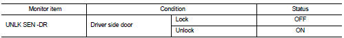
Is the inspection result normal? YES >> Unlock sensor is OK.
NO >> Refer to DLK-104, "Diagnosis Procedure".
Diagnosis Procedure
1.CHECK BCM OUTPUT SIGNAL
1. Turn ignition switch OFF.
2. Disconnect front door lock assembly (driver side) connector.
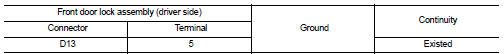
3. Check signal between front door lock assembly (driver side) harness connector and ground using oscilloscope.
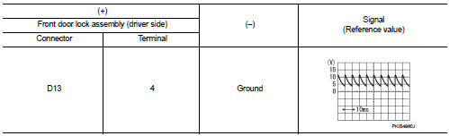
Is the inspection result normal? YES >> GO TO 3.
NO >> GO TO 2.
2.CHECK UNLOCK SENSOR CIRCUIT
1. Disconnect BCM connector.
2. Check continuity between BCM harness connector and front door lock assembly (driver side) harness connector
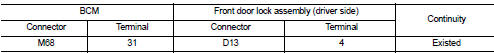
3. Check continuity between BCM harness connector and ground.
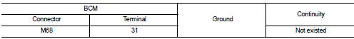
Is the inspection result normal? YES >> Replace BCM. Refer to BCS-93, "Removal and Installation".
NO >> Repair or replace harness.
3.CHECK UNLOCK SENSOR GROUND CIRCUIT
Check continuity between front door lock assembly (driver side) harness connector and ground.
Is the inspection result normal? YES >> GO TO 4.
NO >> Repair or replace harness.
4.CHECK UNLOCK SENSOR
Refer to DLK-105, "Component Inspection".
Is the inspection result normal? YES >> GO TO 5.
NO >> Replace front door lock assembly (driver side).
5.CHECK INTERMITTENT INCIDENT
Refer to GI-42, "Intermittent Incident".
>> INSPECTION END
Component Inspection
1.CHECK UNLOCK SENSOR
1. Turn ignition switch OFF.
2. Disconnect front door lock assembly (driver side) connector.
3. Check continuity between front door lock assembly (driver side) terminals.
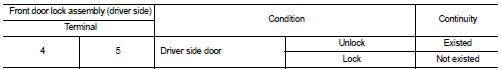
Is the inspection result normal? YES >> INSPECTION END
NO >> Replace front lock assembly (driver side).
 Super lock actuator
Driver side : Component Function Check
1.CHECK FUNCTION
1. Select “DOOR LOCK” of “BCM” using CONSULT-III.
2. Select “SUPER LOCK” in “ACTIVE TEST” mode.
3. Check that the function operates normally ...

Other materials:
Squeak and rattle trouble diagnoses
Work Flow
CUSTOMER INTERVIEW
Interview the customer if possible, to determine the conditions that exist
when the noise occurs. Use the Diagnostic
Worksheet during the interview to document the facts and conditions when the
noise occurs and any of
the customer's comments; refer to DLK-437, ...
Removal and Installation Procedure for CVT Unit Connector
REMOVAL
Rotate bayonet ring (1) counterclockwise, pull out CVT unit harness
connector (2) upward and remove it.
INSTALLATION
1. Align Δ marking on CVT unit harness connector terminal body
with marking on bayonet ring, insert CVT unit harness connector,
and then rotate bayonet ...
U0415 vehicle speed
Description
U0415 is displayed if any unusual condition is present in the reception
status of the vehicle speed signal from
the ABS actuator and electric unit (control unit).
DTC Logic
DTC DETECTION LOGIC
DTC CONFIRMATION PROCEDURE
1.DTC CONFIRMATION
1. Erase the DTC.
2. Turn ignition sw ...
