Nissan Juke Service and Repair Manual : Unit disassembly and assembly
Torque converter and converter housing oil seal
Exploded View
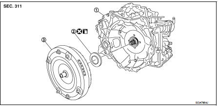
1. Transaxle assembly 2. Converter housing oil seal 3. Torque converter
 : Always replace after every
disassembly.
 : Apply CVT Fluid NS-2.
Disassembly
1. Remove transaxle assembly. Refer to TM-301, "Removal and Installation".
2. Remove torque converter from transaxle assembly.
CAUTION:
Never damage bush on the inside of torque converter sleeve when removing torque
converter.
3. Remove converter housing oil seal using a flat-bladed screwdriver.
CAUTION:
Be careful not to scratch converter housing.
Assembly
Note the following, and install in the reverse order of removal.
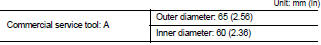
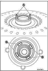
• Drive converter housing oil seal (1) evenly using a drift (A) (commercial service tool) so that converter housing oil seal protrudes by the dimension (B) respectively.
2 : Transaxle assembly

NOTE
:
Converter housing oil seal pulling direction is used as the reference.
• After completing installation, check for CVT fluid leakage and CVT fluid level. Refer to TM-184, "Inspection".
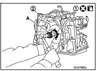
• Attach the pawl (A) of the torque converter to the drive sprocket hole (B) on the transaxle assembly side.
CAUTION:
• Rotate the torque converter for installing torque converter.
• Never damage the bushing inside the torque converter sleeve when installing the converter housing oil seal.
Inspection
INSPECTION AFTER INSTALLATION
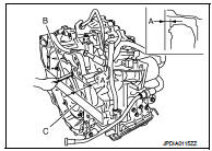
• After inserting a torque converter to the CVT, check dimension (A) with in the reference value limit.
B : Scale
C : Straightedge
Dimension (A) : Refer to TM-308, "Torque Converter".
 Unit removal and installation
Transaxle assembly
Exploded View
1. CVT fluid level gauge
2. CVT fluid charging pipe
3. O-ring
4. Transaxle assembly
5. Air breather hose
A. For tightening torque, refer to TM-301, "R ...

Other materials:
P2120 APP sensor
DTC Logic
DTC DETECTION LOGIC
Diagnosis Procedure
1.CHECK GROUND CONNECTIONS
1. Turn ignition switch OFF.
2. Check ground connection E38. Refer to Ground inspection in GI-44, "Circuit
Inspection".
Is the inspection result normal?
YES >> GO TO 2.
NO >> Repair or ...
Diagnosis system (IPDM E/R)
With intelligent key
WITH INTELLIGENT KEY : Diagnosis Description
AUTO ACTIVE TEST
Description
In auto active test mode, the IPDM E/R sends a drive signal to the following
systems to check their operation.
• Oil pressure warning lamp (only for K9K engine models)
• Rear window defogger
• F ...
System
WITH AUTO A/C
WITH AUTO A/C : System Diagram
WITH AUTO A/C : System Description
OPERATION DESCRIPTION
• BCM detects that the rear window defogger switch turns ON when the ignition
switch is ON, and then transmits
the rear window defogger switch signal to IPDM E/R via CAN communication for
...
