Nissan Juke Service and Repair Manual : U1000 can comm circuit
Description
CAN (Controller Area Network) is a serial communication line for real time application. It is an on-vehicle multiplex communication line with high data communication speed and excellent error detection ability. Many electronic control units are equipped onto a vehicle, and each control unit shares information and links with other control units during operation (not independent). In CAN communication, control units are connected with 2 communication lines (CAN-H line, CAN-L line) allowing a high rate of information transmission with less wiring.
Each control unit communicate data but selectively reads required data only.
DTC Logic
DTC DETECTION LOGIC
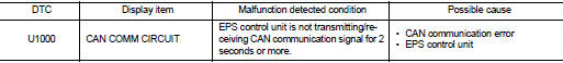
DTC CONFIRMATION PROCEDURE
1.PRECONDITIONING
If “DTC CONFIRMATION PROCEDURE” has been previously conducted, always turn ignition switch OFF and wait at least 10 seconds before conducting the next test.
>> GO TO 2.
2.DTC REPRODUCTION PROCEDURE
 With CONSULT-III
1. Turn the ignition switch OFF to ON.
2. Perform “EPS” self-diagnosis.
Is DTC “U1000” detected? YES >> Proceed to diagnosis procedure. Refer to STC-25, "Diagnosis Procedure".
NO >> INSPECTION END
Diagnosis Procedure
Proceed to LAN-17, "Trouble Diagnosis Flow Chart".
 C1609 vehicle speed signal
DTC Logic
DTC DETECTION LOGIC
DTC CONFIRMATION PROCEDURE
1.PRECONDITIONING
If “DTC CONFIRMATION PROCEDURE” has been previously conducted, always turn
ignition switch OFF and
wait at least 10 ...
 EPS warning lamp
Component Function Check
1.CHECK THE ILLUMINATION OF THE EPS WARNING LAMP
Check that the EPS warning lamp turns ON when ignition switch turns ON. Then,
EPS warning lamp turns
OFF after the engine ...
Other materials:
System
AUTO RETRACTABLE DOOR MIRORR FUNCTION
AUTO RETRACTABLE DOOR MIRORR FUNCTION : System Diagram
AUTO RETRACTABLE DOOR MIRORR FUNCTION : System Description
BCM retracts door mirror when door lock signal is received from Intelligent
Key or door request switch.
OPERATION CONDITION
The system oper ...
P0544 EGT sensor 1
DTC Logic
DTC DETECTION LOGIC
Diagnosis Procedure
1.CHECK GROUND CONNECTIONS
1. Turn ignition switch OFF.
2. Check ground connection E38. Refer to Ground inspection in GI-44, "Circuit
Inspection".
Is the inspection result normal?
YES >> GO TO 2.
NO >> Repair or ...
Removal and Installation
REMOVAL
1. Remove engine assembly. Refer to EM-55, "2WD : Exploded View" (2WD) ,
EM-59, "4WD : Exploded
View" (4WD).
2. Remove oil pan (lower). Refer to EM-41, "Removal and Installation".
3. Remove front cover, and other related parts. Refer to EM-67, "Explod ...
