Nissan Juke Service and Repair Manual : U1000 can comm circuit
Description
CAN (Controller Area Network) is a serial communication line for real time application. It is an on-vehicle multiplex communication line with high data communication speed and excellent malfunction detection ability.
Many electronic control units are equipped onto a vehicle, and each control unit shares information and links with other control units during operation (not independent). In CAN communication, control units are connected with 2 communication lines (CAN-H and CAN-L) allowing a high rate of information transmission with less wiring. Each control unit transmits/receives data but selectively reads required data only.
DTC Logic
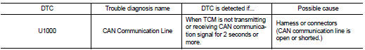
DTC DETECTION LOGIC
DTC CONFIRMATION PROCEDURE
NOTE
:
If “DTC CONFIRMATION PROCEDURE” has been previously performed, always turn
ignition switch
OFF and wait at least 10 seconds before performing the next test.
After the repair, perform the following procedure to confirm the malfunction is eliminated.
1.CHECK DTC DETECTION
 With CONSULT-III
1. Turn ignition switch ON.
2. Start engine and wait for at least 6 seconds.
3. Select “Self Diagnostic Results” in “TRANSMISSION”.
 With GST
Follow the procedure “With CONSULT-III”.
Is “U1000” detected? YES >> Go to TM-195, "Diagnosis Procedure".
NO >> Check intermittent incident. Refer to GI-42, "Intermittent Incident".
Diagnosis Procedure
Go to LAN-17, "Trouble Diagnosis Flow Chart"

 U1010 control unit (CAN)
Description
CAN (Controller Area Network) is a serial communication line for real time
application. It is an on-vehicle multiplex
communication line with high data communication speed and excellen ...
Other materials:
A/C indicator
Diagnosis Procedure
1.CHECK SYMPTOM
Check symptom.
A/C indicator dose not turn ON>>GO TO 2.
A/C indicator dose not turn OFF>>GO TO 6.
2.CHECK FUSE
1. Turn ignition switch OFF.
2. Check 10A fuse (No. 15, located in fuse block (J/B)].
NOTE:
Refer to PG-22, "Fuse, Conn ...
Rear power window switch
Component Function Check
1. CHECK REAR POWER WINDOW SWITCH FUNCTION
Check rear power window motor operation with rear power window switch.
Is the inspection result normal?
YES >> INSPECTION END
NO >> Refer to PWC-24, "Diagnosis Procedure".
Diagnosis Procedure
1.CHECK R ...
Symptom diagnosis
CVT CONTROL SYSTEM
Symptom Table
The diagnosis item number indicates the order of check. Start checking in the
order from 1.
...
