Nissan Juke Service and Repair Manual : U1000 can comm
Description
CAN (Controller Area Network) is a serial communication line for real time applications. It is an on-vehicle multiplex communication line with high data communication speed and excellent error detection ability. Modern vehicle is equipped with many electronic control unit, and each control unit shares information and links with other control units during operation (not independent). In CAN communication, control units are connected with 2 communication lines (CAN H-line, CAN L-line) allowing a high rate of information transmission with less wiring. Each control unit transmits/receives data but selectively reads required data only.
CAN Communication Signal Chart. Refer to LAN-31, "CAN COMMUNICATION SYSTEM : CAN Communication Signal Chart".
DTC Logic
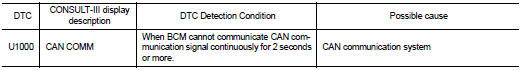
DTC DETECTION LOGIC
Diagnosis Procedure
1.PERFORM SELF DIAGNOSTIC
1. Turn ignition switch ON and wait for 2 seconds or more.
2. Check “Self Diagnostic Result” of BCM.
Is DTC “U1000” displayed? YES >> Refer to LAN-17, "Trouble Diagnosis Flow Chart".
NO >> Refer to GI-42, "Intermittent Incident".

 U1010 control unit (can)
DTC Logic
DTC DETECTION LOGIC
Diagnosis Procedure
1.REPLACE BCM
When DTC “U1010” is detected, replace BCM.
>> Replace BCM. Refer to BCS-93, "Removal and Installation". ...
Other materials:
P1550 battery current sensor
DTC Logic
DTC DETECTION LOGIC
DTC CONFIRMATION PROCEDURE
1.PRECONDITIONING
If DTC Confirmation Procedure has been previously conducted, always perform
the following before conducting
the next test.
1. Turn ignition switch OFF and wait at least 10 seconds.
2. Turn ignition switch ON.
3. ...
P2138 APP sensor
DTC Logic
DTC DETECTION LOGIC
NOTE:
If DTC P2138 is displayed with DTC P0643, first perform the trouble diagnosis
for DTC P0643. Refer to
EC-686, "DTC Logic".
DTC CONFIRMATION PROCEDURE
1.PRECONDITIONING
If DTC Confirmation Procedure has been previously conducted, always turn
...
Hazard function
Component Function Check
1.CHECK FUNCTION
1. Select “MULTI REMOTE ENT” of “BCM” using CONSULT-III.
2. Select “FLASHER” in “ACTIVE TEST” mode.
3. Check that the function operates normally according to the following
conditions.
Is the inspection result normal?
YES >> Hazard warning lam ...
