Nissan Juke Service and Repair Manual : U0101 Can comm circuit
Description
CAN (Controller Area Network) is a serial communication line for real time application. It is an on-vehicle multiplex communication line with high data communication speed and excellent error detection ability. Many electronic control units are equipped onto a vehicle, and each control unit shares information and links with other control units during operation (not independent). In CAN communication, control units are connected with 2 communication lines (CAN H line, CAN L line) allowing a high rate of information transmission with less wiring.
Each control unit transmits/receives data but selectively reads required data only.
DTC Logic
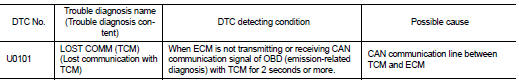
DTC DETECTION LOGIC
DTC CONFIRMATION PROCEDURE
1.PERFORM DTC CONFIRMATION PROCEDURE
1. Turn ignition switch ON and wait at least 3 seconds.
2. Check DTC.
Is DTC detected? YES >> Proceed to EC-159, "Diagnosis Procedure".
NO >> INSPECTION END
Diagnosis Procedure
Perform the trouble diagnosis for CAN communication system. Refer to LAN-17, "Trouble Diagnosis Flow Chart".
 Power supply and ground circuit
Diagnosis Procedure
1.CHECK FUSE
Is the fuse fusing?
YES >> Replace the fuse after repairing the applicable circuit.
NO >> GO TO 2.
2.CHECK GROUND CONNECTION
1. Turn ignition swi ...
 U0122 Vehicle dynamics control
module
U0122 Vehicle dynamics control
module
Description
CAN (Controller Area Network) is a serial communication line for real time
application. It is an on-vehicle multiplex
communication line with high data communication speed and excelle ...
Other materials:
Front power window switch (passenger side)
Component Function Check
1. CHECK FRONT POWER WINDOW SWITCH (PASSENGER SIDE) FUNCTION
Check front power window motor (passenger side) operation with front power
window switch (passenger side).
Is the inspection result normal?
YES >> INSPECTION END
NO >> Refer to PWC-22, "Di ...
Map lamp
Exploded View
1. Map lamp bulb housing
2. Bulb
3. Lens
: Pawl
Removal and Installation
CAUTION:
Disconnect the battery negative terminal or the fuse.
REMOVAL
1. Remove the lens (1).
• Insert a remover tool (A) into the gap between the lens.
• Disengage the lens fixing pawls, and then ...
ECU diagnosis information
ABS actuator and electric unit (control unit)
Reference Value
CONSULT-III DATA MONITOR STANDARD VALUE
*1: Confirm tire pressure is standard value.
*2: Refer to “valve operation” in BRC-105, "System Description" for valve
operation of each valve.
*3: Refer to BRC-105, "Sys ...
