Nissan Juke Service and Repair Manual : Turbocharger boost control
Turbocharger boost control : SystemDiagram
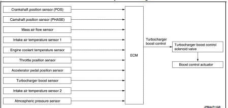
Turbocharger boost control : System Description
INPUT/OUTPUT SIGNAL CHART
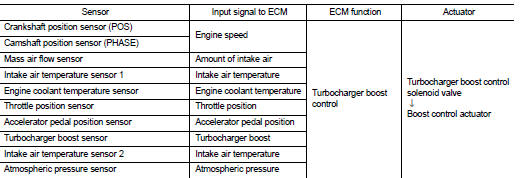
SYSTEM DESCRIPTION
Depending on driving conditions, the ECM performs ON/OFF duty control of the turbocharger boost control solenoid valve and controls the boost by adjusting the pressure to the diaphragm of the boost control actuator.
When driving conditions demand an increase in boost, the ECM prolongs the ON time of the turbocharger boost control solenoid valve and moves the boost control valve towards the closing direction by reducing the pressure in the diaphragm of the boost control actuator. The emission gas to the turbine wheel is then increased. When driving conditions demand a decrease in boost, the ECM shortens the ON time of the turbocharger boost control solenoid valve and moves the boost control valve towards the opening position by increasing the pressure in the diaphragm of the boost control actuator. The emission bypassing to the turbine wheel is then increased. Thus, by performing the most optimal boost control, the ECM improves engine output and response.
NOTE
:
The boost varies depending on the vehicle and driving conditions.
BOOST CONTROL ACTUATOR LINE DRAWING
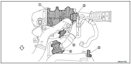
1. Turbocharger
2. Boost control actuator
3. Turbocharger boost control solenoid
valve
4. Recirculation valve
5. Turbocharger boost sensor
(with intake air temperature sensor 2)
 : Vehicle front
 Exhaust valve timing control
Exhaust valve timing control : System Diagram
Exhaust valve timing control: System Description
INPUT/OUTPUT SIGNAL CHART
SYSTEM DESCRIPTION
This mechanism hydraulically controls cam phases c ...
 Engine protection control at low engine oil pressure
Engine protection control at low engine oil pressure : System Diagram
Engine protection control at low engine oil pressure : System Description
INPUT/OUTPUT SIGNAL CHART
SYSTEM DESCRIPTION
• ...
Other materials:
P0197, P0198 EOT sensor
DTC Logic
DTC DETECTION LOGIC
DTC CONFIRMATION PROCEDURE
1.PRECONDITIONING
If DTC Confirmation Procedure has been previously conducted, always perform
the following procedure
before conducting the next test.
1. Turn ignition switch OFF and wait at least 10 seconds.
2. Turn ignition swit ...
B210D starter relay
DTC Logic
DTC DETECTION LOGIC
NOTE:
If DTC B210D is displayed with DTC U1000, first perform the trouble diagnosis
for DTC U1000. Refer to PCS-
30, "DTC Logic".
DTC CONFIRMATION PROCEDURE
1.PERFORM DTC CONFIRMATION PROCEDURE 1
1. Press push-button ignition switch under the follow ...
Liquid Gasket
REMOVAL OF LIQUID GASKET SEALING
• After removing mounting nuts and bolts, separate the mating surface
using the seal cutter [SST: KV10111100] (A) and remove old
liquid gasket sealing.
CAUTION:
Be careful not to damage the mating surfaces.
• Tap the seal cutter [SST: KV10111100] to insert it ...
