Nissan Juke Service and Repair Manual : Turbocharger
Exploded View
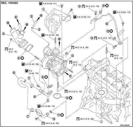
1. Heat insulator
2. Actuator hose
3. Clamp
4. Turbocharger inlet tube
5. Gasket
6. Gasket
7. Clamp
8. Oil outlet hose
9. Oil return pipe
10. Oil supply tube
11. O-ring
12. O-ring
13. Turbocharger
14. Eye bolt
15. Gasket
16. Oil supply tube
A. To EVAP canister purge volume control
solenoid valve
B. To air inlet hose
C. To PCV hose
D. To air duct E. To air inlet tube assembly F. To catalyst convertor
 : N·m (kg-m, ft-lb)
 : N·m (kg-m, in-lb)
 : Always replace after every
disassembly.
Removal and Installation
REMOVAL
1. Drain engine coolant. Refer to CO-11, "Draining".
2. Remove engine cover. Refer to EM-25, "Exploded View".
3. Remove air cleaner cover assembly and air cleaner body assembly. Refer to EM-26, "Exploded View".
4. Remove air inlet tube assembly. Refer to EM-31, "Exploded View".
5. Remove cowl top extension. Refer to EXT-20, "Exploded View".
6. Disconnect heated oxygen sensor 2 harness connector.
7. Remove front tube. Refer to EX-5, "Exploded View".
8. Remove catalyst convertor. Refer to EM-33, "2WD : Exploded View" (2WD models) or EM-34, "4WD : Exploded View" (4WD models).
9. Remove turbocharger assembly as follows:
a. Remove heat insulator.
b. Remove oil supply tube.
c. Remove mounting nuts of turbocharger.
CAUTION:
Be careful not to deform each turbocharger piping when pulling out the assembly.
INSTALLATION
Install in the reverse order of removal.
NOTE
:
Apply LOCTITE FRENETANCH or equivalent to the threads of the turbocharger oil inlet pipe union to the cylinder head
Inspection
Turbocharger
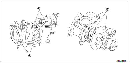
A. Check for leakage
CAUTION:
When the compressor wheel, turbine wheel or rotor shaft is damaged, remove all
the fragments and
foreign matter left in the following passages in order to prevent a secondary
failure:
Suction side : Between turbocharger and air cleaner Exhaust side : Between turbocharger and outlet duct
INSPECTION AFTER INSTALLATION
Start engine and raise engine speed to check no exhaust emission leaks.
 Catalyst
2WD
2WD : Exploded View
1. A/F sensor 1
2. Catalyst convertor shroud upper
3. Gasket
4. Catalyst
5. Catalyst convertor support bracket rear
6. Catalyst convertor bracket (RH)
A. To exhau ...
 Exhaust manifold
Exploded View
1. Stud bolt
2. Exhaust manifold cover
3. Exhaust manifold
4. Gasket
Engine front
: N·m (kg-m, ft-lb)
: N·m (kg-m, in-lb)
: Always replace after every
disassembly.
Remova ...
Other materials:
System
Intelligent key system/engine start function
INTELLIGENT KEY SYSTEM/ENGINE START FUNCTION : System Diagram
INTELLIGENT KEY SYSTEM/ENGINE START FUNCTION : System
SYSTEM DESCRIPTION
• The engine start function of Intelligent Key system makes it possible to
start and stop the engine without
us ...
Inspection
LEVEL
• Check that the reservoir tank engine coolant level is within the
“MIN” to “MAX” when the engine is cool.
A : MAX
B : MIN
• Adjust the engine coolant level if necessary.
LEAKAGE
• To check for leakage, apply pressure to the cooling system with the
radiator cap tester (commercial ser ...
Headlining
Exploded View
LHD models
1. Headlining assembly
2. Assist grip clip
3. Rear assist grip RH
4. Front assist grip RH
5. Sun visor assembly RH
6. Sun visor cover RH
7. Sun visor cover LH
8. Sun visor assembly LH
9. Rear assist grip LH
10. Headlining clip
11. Sun visor holder RH
1 ...
