Nissan Juke Service and Repair Manual : Trouble diagnosis
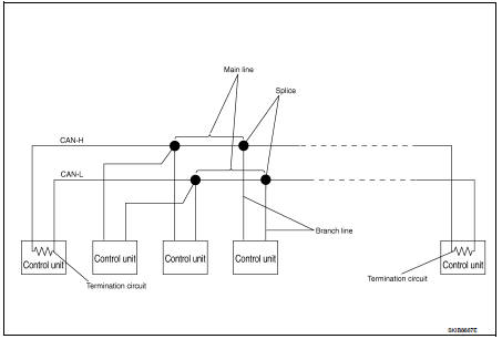
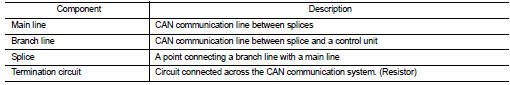
System Diagram
Condition of Error Detection
DTC (e.g. U1000 and U1001) of CAN communication is indicated on SELF-DIAG RESULTS on CONSULT-III if a CAN communication signal is not transmitted or received between units for 2 seconds or more.
CAN COMMUNICATION SYSTEM ERROR
• CAN communication line open (CAN-H, CAN-L, or both)
• CAN communication line short (ground, between CAN communication lines, other
harnesses)
• Error of CAN communication control circuit of the unit connected to CAN
communication line
WHEN DTC OF CAN COMMUNICATION IS INDICATED EVEN THOUGH CAN COMMUNICATION SYSTEM IS NORMAL
• Removal/installation of parts: Error may be detected when removing and
installing CAN communication unit
and related parts while turning the ignition switch ON. (A DTC except for CAN
communication may be
detected.)
• Fuse blown out (removed): CAN communication of the unit may cease.
• Voltage drop: Error may be detected if voltage drops due to discharged battery when turning the ignition switch ON (Depending on the control unit which carries out CAN communication).
• Error may be detected if the power supply circuit of the control unit, which carries out CAN communication, malfunctions (Depending on the control unit which carries out CAN communication).
• Error may be detected if reprogramming is not completed normally.
CAUTION
:
CAN communication system is normal if DTC of CAN communication is indicated on
SELF-DIAG
RESULTS of CONSULT-III under the above conditions. Erase the memory of the
self-diagnosis of each
unit.
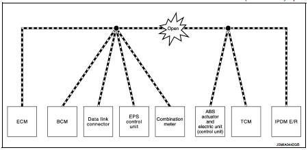
Symptom When Error Occurs in CAN Communication System
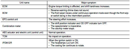
In CAN communication system, multiple units mutually transmit and receive signals. Each unit cannot transmit and receive signals if any error occurs on CAN communication line. Under this condition, multiple control units related to the root cause malfunction or go into fail-safe mode.
ERROR EXAMPLE
NOTE
:
Each vehicle differs in symptom of each unit under fail-safe mode and CAN
communication line wiring.
Example: Main Line Between Data Link Connector and ABS Actuator and Electric Unit (Control Unit) Open Circuit
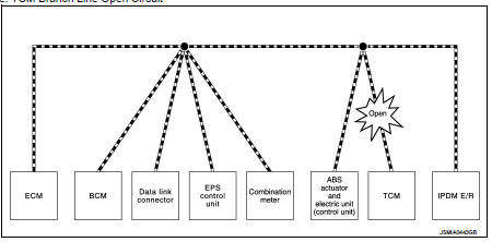
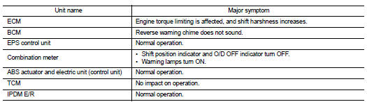
Example: TCM Branch Line Open Circuit
NOTE
:
The model (all units on CAN communication system are Diag on CAN) cannot perform
CAN diagnosis with
CONSULT-III if the following error occurs. The error is judged by the symptom.
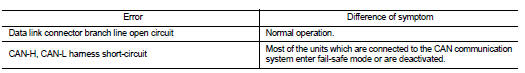
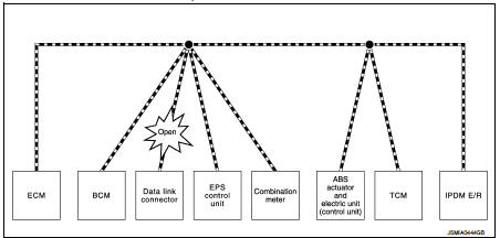
Example: Data Link Connector Branch Line Open Circuit
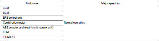
NOTE
:
When data link connector branch line is open, transmission and reception of CAN
communication signals are
not affected. Therefore, no symptoms occur. However, be sure to repair
malfunctioning circuit.
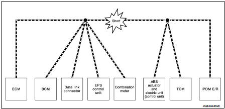
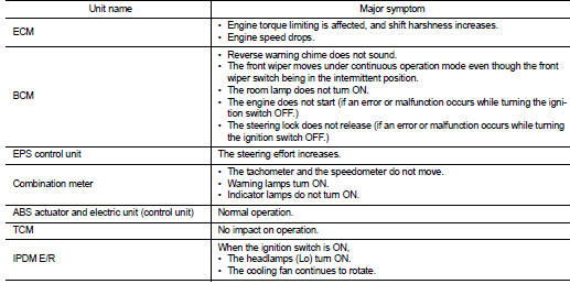
Example: CAN-H, CAN-L Harness Short Circuit
Can diagnosis with consult-III
CAN diagnosis on CONSULT-III extracts the root cause by receiving the following information.
• Response to the system call
• Control unit diagnosis information
• Self-diagnosis
• CAN diagnostic support monitor
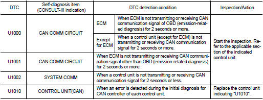
Self-Diagnosis
If communication signals cannot be transmitted or received among units communicating via CAN communication line, CAN communication-related DTC is displayed on the CONSULT-III “Self Diagnostic Result” screen.
NOTE
:
The following table shows examples of CAN communication-related DTC. For other
DTC, refer to the applicable
sections.
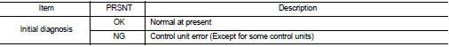
Can Diagnostic Support Monitor
MONITOR ITEM (CONSULT-III)
Example: CAN DIAG SUPPORT MNTR indication
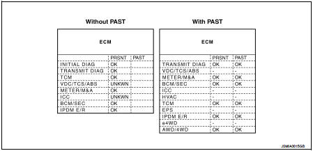
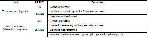
Without PAST
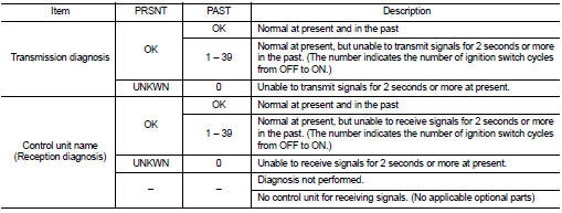
With PAST
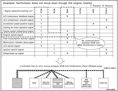
How to Use Can Communication Signal Chart
The CAN communication signal chart lists the signals needed for trouble diagnosis. It is useful for detecting the root cause by finding a signal related to the symptom, and by checking transmission and reception unit.
 System
Can communication system
CAN COMMUNICATION SYSTEM : System Description
CAN (Controller Area Network) is a serial communication line for real time
application. It is an on-vehicle multiplex
commun ...
 Basic inspection
Diagnosis and repair workflow
Trouble Diagnosis Flow Chart
Trouble Diagnosis Procedure
INTERVIEW WITH CUSTOMER
Interview with the customer is important to detect the root cause of CAN
communic ...
Other materials:
P158A ECM
DTC Logic
*: Since this DTC is detected when G sensor calibration is incomplete, there
is not replacement parts.
1.PRECONDITIONING
If DTC Confirmation Procedure has been previously conducted, always perform
the following procedure
before conducting the next test.
1. Turn ignition swit ...
NISSAN Vehicle Immobilizer System keys
Your vehicle can only be driven with the master keys which are registered to
the NISSAN Vehicle Immobilizer System components in your vehicle. These keys have
a transponder chip in the key head.
Never leave these keys in the vehicle. Additional or replacement keys:
If you still have a key, the ...
Diagnosis and repair work flow
Work Flow
OVERALL SEQUENCE
DETAILED FLOW
1.GET INFORMATION ABOUT SYMPTOM
Get the detailed information from the customer about the symptom (the
condition and the environment when
the incident/malfunction occurred).
>> GO TO 2.
2.CHECK DTC
1. Check DTC for “ENGINE” and “BCM” usin ...
