Nissan Juke Service and Repair Manual : Transverse link
Exploded View
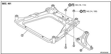
1. Front suspension member 2. Transverse link
 : Always replace after every
disassembly.
 : N·m (kg-m, ft-lb)
Removal and Installation
REMOVAL
1. Remove tires. Refer to WT-7, "Removal and Installation".
2. Remove transverse link from steering knuckle.
• MR16DDT: Refer to FAX-11, "Removal and Installation".
• HR16DE: Refer to FAX-43, "Removal and Installation".
• K9K: Refer to FAX-68, "Removal and Installation".
3. Remove transverse link from suspension member.
INSTALLATION
Note the following, and install in the reverse order of removal.
• Never reuse transverse link mounting nut.
• Perform final tightening of bolts and nuts at the vehicle installation position (rubber bushing), under unladen conditions with tires on level ground.
• Perform inspection after installation. Refer to FSU-14, "Inspection".
Inspection
INSPECTION AFTER REMOVAL
Check the following items, and replace the parts if necessary.
Transverse Link
• Transverse link and bushing for deformation, cracks or damage.
• Ball joint boot for cracks or other damage, and also for grease leakage.
Swing Torque
1. Manually move ball stud to confirm it moves smoothly with no binding.
2. Move ball stud at least ten times by hand to check for smooth movement.
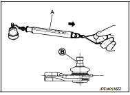
3. Hook a spring balance (A) at cutout on ball stud (B). Confirm spring balance measurement value is within specifications when ball stud begins moving.
Swing torque : Refer to FSU-22, "Ball Joint".
Measurement on spring balance : Refer to FSU-22, "Ball Joint"
• If swing torque exceeds standard range, replace transverse link assembly.
Axial End Play
1. Move ball stud at least ten times by hand to check for smooth movement.
2. Move tip of ball stud in axial direction to check for looseness.
Axial end play : Refer to FSU-22, "Ball Joint".
• If axial end play exceeds the standard value, replace transverse link assembly.
INSPECTION AFTER INSTALLATION
Check wheel alignment. Refer to FSU-7, "Inspection".
 Front coil spring and strut
Exploded View
2WD
1. Piston rod lock nut
2. Mounting insulator
3. Mounting bearing
4. Bound bumper
5. Coil spring
6. Lower rubber seat
7. Strut
8. Steering knuckle
: N·m (kg-m, ft-lb) ...
 Front stabilizer
Exploded View
1. Stabilizer bar
2. Stabilizer clamp
3. Stabilizer bushing
4. Stabilizer connecting rod
5. Strut assembly
6. Front suspension member
: N·m (kg-m, ft-lb)
Removal and Instal ...
Other materials:
Forward-facing child restraint installation using LATCH
Refer to all Warnings and Cautions in the “Child safety” and “Child restraints”
sections before installing a child restraint.
Follow these steps to install a forward-facing child restraint using the LATCH
system:
1. Position the child restraint on the seat.
Always follow the child restraint m ...
The key warning does not sound (without intelligent key)
Description
The key warning chime does not sound, when all of the following conditions
are fulfilled.
• Key inserted into the key cylinder (key switch signal ON).
• Ignition switch is in ACC or OFF (ignition switch signal OFF).
• Driver side door is open (driver side door switch ON)
Diagnos ...
Electric power steering system
WARNING
• If the engine is not running or is turned off while driving, the power assist
for the steering will not work.
Steering will be harder to operate.
• When the electric power steering warning light illuminates with the engine
running, the power assist for the steering will cease ...
