Nissan Juke Service and Repair Manual : Thermo control amplifier
Component Function Check
1.CHECK A/C ON SIGNAL
 With CONSULT-III
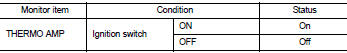
1. Turn ignition switch ON.
2. Select “AIR CONDITIONER” of “BCM” using CONSULT-III.
3. Select “THERMO AMP” in “DATA MONITOR” mode, and check status under the following condition.
Is the inspection result normal? YES >> INSPECTION END
NO >> Refer to HAC-224, "Diagnosis Procedure".
Diagnosis Procedure
1.CHECK FUSE
1. Turn ignition switch OFF.
2. Check 10A fuse (No. 15, located in fuse block (J/B)].
NOTE
:
Refer to PG-22, "Fuse, Connector and Terminal Arrangement".
Is the inspection result normal? YES >> GO TO 2.
NO >> Replace the blown fuse after repairing the affected circuit if a fuse is blown.
2.CHECK THERMO CONTROL AMP. POWER SUPPLY
1. Turn ignition switch OFF.
2. Disconnect thermo control amp. connector.
3. Turn ignition switch ON.
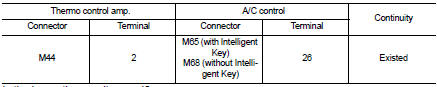
4. Check voltage between thermo control amp. harness connector and ground.
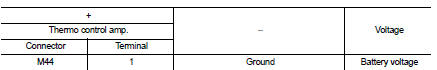
Is the inspection result normal? YES >> GO TO 3.
NO >> Repair harness or connector between thermo control amp. and fuse.
3.CHECK THERMO CONTROL AMP. GROUND CIRCUIT FOR OPEN
1. Turn ignition switch OFF.
2. Check continuity between thermo control amp. harness connector and ground.
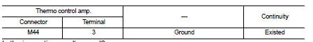
Is the inspection result normal? YES >> GO TO 4.
NO >> Repair harness or connector.
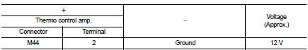
4.CHECK THERMO CONTROL AMP. SIGNAL
1. Turn ignition switch ON.
2. Check voltage between thermo control amp. harness connector and ground.
Is the inspection result normal? YES >> Replace thermo control amp. Refer to HAC-240, "Removal and Installation".
NO >> GO TO 5.
5.CHECK THERMO CONTROL AMP. SIGNAL CIRCUIT FOR OPEN
1. Turn ignition switch OFF.
2. Disconnect BCM connector.
3. Check continuity between thermo control amp. harness connector and BCM harness connector.
Is the inspection result normal? YES >> Replace BCM. Refer to BCS-93, "Removal and Installation" (with Intelligent Key) or BCS-161, "Removal and Installation" (without Intelligent Key).
NO >> Repair harness or connector.
 Blower fan on signal
Component Function Check
1.CHECK BLOWER FAN ON SIGNAL
With CONSULT-III
1. Turn ignition switch ON.
2. Select “AIR CONDITIONER” of “BCM” using CONSULT-III.
3. Select “FAN ON SIG” in “DATA MONITOR” ...
 A/C indicator
Diagnosis Procedure
1.CHECK SYMPTOM
Check symptom.
A/C indicator dose not turn ON>>GO TO 2.
A/C indicator dose not turn OFF>>GO TO 6.
2.CHECK FUSE
1. Turn ignition switch OFF.
...
Other materials:
P182D 4WD solenoid left
DTC Logic
DTC DETECTION LOGIC
DTC CONFIRMATION PROCEDURE
1.PRECONDITIONING
If “DTC CONFIRMATION PROCEDURE” has been previously conducted, always turn
ignition switch OFF and
wait at least 10 seconds before conducting the next test.
>> GO TO 2.
2.DTC REPRODUCTION PROCEDURE (1)
W ...
P0606 ECM
DTC Logic
DTC DETECTION LOGIC
Diagnosis Procedure
1.INSPECTION START
1. Turn ignition switch ON.
2. Erase DTC.
3. Turn ignition switch OFF and wait for 20 seconds.
4. Turn ignition switch ON and perform the self-diagnosis.
Is the DTC P0606 displayed again?
YES >> GO TO 2.
NO &g ...
Key out interlock door unlock function does not operate
Diagnosis Procedure
1.CHECK “AUTOMATIC LOCK/UNLOCK SELECT” SETTING IN “WORK SUPPORT”
1. Select “DOOR LOCK” of “BCM” using CONSULT-III.
2. Select “AUTOMATIC LOCK/UNLOCK SELECT” in “WORK SUPPORT” mode.
3. Check “AUTOMATIC LOCK/UNLOCK SELECT” in “WORK SUPPORT”.
Refer to DLK-501, "DOOR LOCK ...
