Nissan Juke Service and Repair Manual : System
Warning chime system
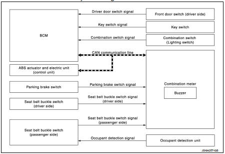
WARNING CHIME SYSTEM : System Diagram
WARNING CHIME SYSTEM : System Description
COMBINATION METER
The combination meter sounds the alarm buzzer installed in the combination meter when receiving the buzzer output signal transmitted from each unit.
BCM
BCM receives signals from various units and transmits a buzzer output signal to
the combination meter via
CAN communication if it judges that the warning buzzer should be activated.
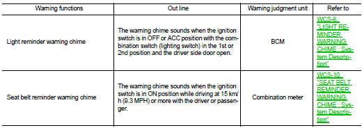
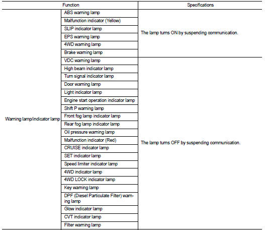
WARNING CHIME FUNCTION LIST
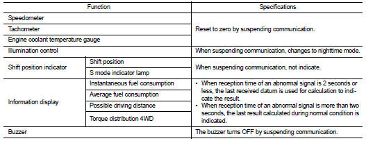
WARNING CHIME SYSTEM : Fail-Safe
FAIL-SAFE
The combination meter activates the fail-safe control if CAN communication with each unit is malfunctioning.
Light reminder warning chime
LIGHT REMINDER WARNING CHIME : System Dia
LIGHT REMINDER WARNING CHIME : System Description
WARNING CHIME OPERATION CONDITIONS
If all of the following conditions are fulfilled.
WARNING CHIME CANCEL CONDITIONS
Warning is canceled if any of the following conditions is fulfilled.
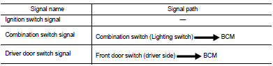
SIGNAL PATH
1. BCM requires warning chime output to combination meter when it judges light reminder warning chime is necessary from signals below.
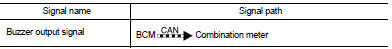
2. Combination meter sounds integrated buzzer, following the warning chime output requirement (below signal) from BCM.
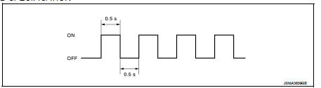
TIMING CHART
Seat belt reminder warning chime
SEAT BELT REMINDER WARNING CHIME : System Diagram
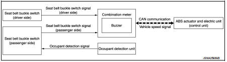
SEAT BELT REMINDER WARNING CHIME : System Description
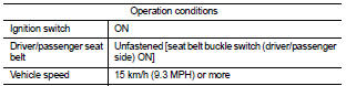
WARNING OPERATION CONDITIONS
If all of the following conditions are fulfilled.
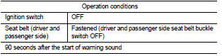
WARNING CANCEL CONDITIONS
Warning is canceled if any of the following conditions is fulfilled.
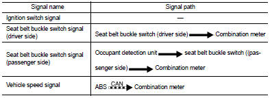
SIGNAL PATH
Combination meter sounds integrated buzzer when it judges that seat belt warning chime is necessary from signals below.
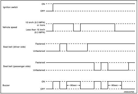
TIMING CHART
SOUND SPECIFICATION
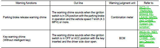
Parking brake release warning chime
PARKING BRAKE RELEASE WARNING CHIME : System Diagram
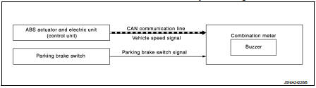
PARKING BRAKE RELEASE WARNING CHIME : System Description
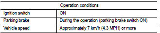
WARNING OPERATION CONDITIONS
If all of the following conditions are fulfilled.
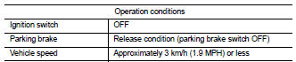
WARNING CANCEL CONDITIONS
Warning is canceled if any of the following conditions are fulfilled.
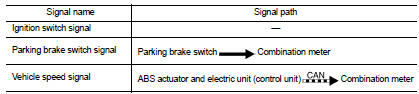
SIGNAL PATH
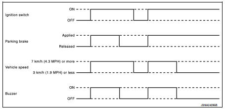
Combination meter sounds integrated buzzer when it judges that parking brake release warning chime is necessary from signals below.
TIMING CHART
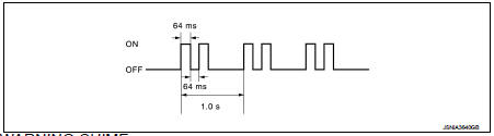
SOUND SPECIFICATION
Key warning chime
KEY WARNING CHIME : System Diagram
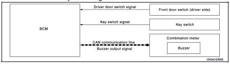
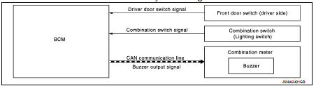
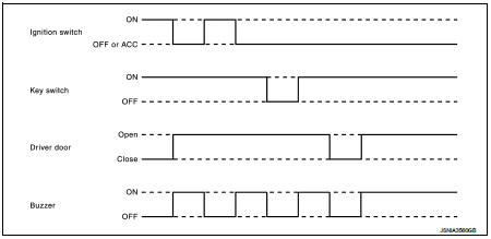
KEY WARNING CHIME : System Description
DESCRIPTION
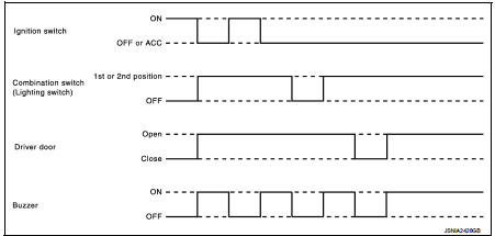
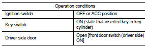
The warning chime sounds when the ignition switch is in OFF or ACC position with the key inserted and the driver side door open.
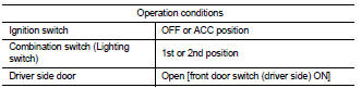
WARNING OPERATION CONDITIONS
The BCM transmits the buzzer output signal to combination meter with CAN communication line when all of the following operation conditions are met. When combination meter receives buzzer output signal, it sounds the buzzer
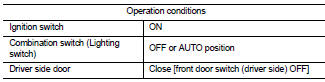
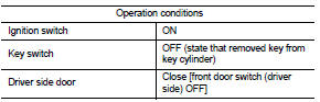
WARNING CANCEL CONDITIONS
Warning is canceled if any of the following conditions is fulfilled.
SIGNAL PATH
1. BCM requires warning chime output to combination meter when it judges key warning chime is necessary from signals below.
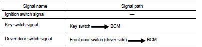
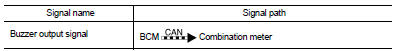
2. Combination meter sounds integrated buzzer, following the warning chime output requirement (below signal) from BCM.
TIMING CHART
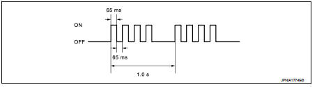
SOUND SPECIFICATION
 Component parts
Component Parts Location
1. Parking brake switch
2. Seat belt buckle switch (passenger
side)
3. Occupant detection unit
(Under the passenger seat cushion
pad)
4. ABS actuator and electric un ...
 Diagnosis system (combination meter)
Consult-III Function
CONSULT-III APPLICATION ITEMS
CONSULT-III can perform the following diagnosis modes via CAN communication
and the combination meter.
SELF DIAG RESULT
Refer to MWI-36, &quo ...
Other materials:
Wiring diagram
POWER DISTRIBUTION SYSTEM
LHD
LHD : Wiring Diagram
For connector terminal arrangements, harness layouts, and alphabets in a
(option abbreviation; if not
described in wiring diagram), refer to GI-12, "Connector Information/Explanation
of Option Abbreviation".
RHD
RHD : Wiring D ...
Removal and Disassembly
• When instructed to use SST, use specified tools. Always be careful to work
safely, avoid forceful or uninstructed
operations.
• Exercise maximum care to avoid damage to mating or sliding surfaces.
• Dowel pins are used for several parts alignment. When replacing and
reassembling parts with ...
Radiator
Exploded View
1. Reservoir tank cap
2. Reservoir tank
3. Clamp
4. Reservoir tank hose
5. Mounting rubber (upper)
6. Reservoir tank hose
7. Radiator
8. Mounting rubber (lower)
9. Drain plug
10. O-ring
11. Cooling fan assembly
12. Radiator hose (upper)
13. Radiator hose (lower)
...
