Nissan Juke Service and Repair Manual : System
Charging system
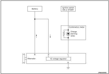
CHARGING SYSTEM : System Diagram
GASOLINE ENGINE MODELS
DIESEL ENGINE MODELS
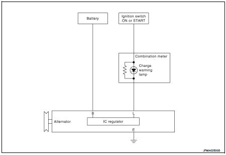
CHARGING SYSTEM : System Description
The alternator provides DC voltage to operate the vehicle's electrical system and to keep the battery charged.
The voltage output is controlled by the IC voltage regulator
Power generation voltage variable control system
POWER GENERATION VOLTAGE VARIABLE CONTROL SYSTEM : System Diagram (Gasoline Engine Models)
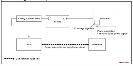
POWER GENERATION VOLTAGE VARIABLE CONTROL SYSTEM : System Description (Gasoline Engine Models)
By performing the power generation voltage variable control, the engine load due to the power generation of the alternator is reduced and fuel consumption is decreased.
NOTE
:
When any malfunction is detected in the power generation voltage variable
control system, the power generation
is performed according to the characteristic of the IC voltage regulator of the
alternator.
 Component parts
Charging system
CHARGING SYSTEM : Component Parts Location
1. Charge warning lamp (On the combination
meter)
2. Alternat
CHARGING SYSTEM : Component Description
Power generation voltage vari ...
 Wiring diagram
CHARGING SYSTEM
Wiring Diagram
GASOLINE ENGINE MODELS
For connector terminal arrangements, harness layouts, and alphabets in a
(option abbreviation; if not
described in wiring diagram), refer to ...
Other materials:
Precaution Necessary for Steering Wheel Rotation after Battery Disconnect
NOTE:
• Before removing and installing any control units, first turn the ignition
switch to the LOCK position, then disconnect
both battery cables.
• After finishing work, confirm that all control unit connectors are connected
properly, then re-connect both
battery cables.
• Always use CONS ...
B210C starter control relay
DTC Logic
DTC DETECTION LOGIC
NOTE:
• If DTC B210C is displayed with DTC U1000, first perform the trouble diagnosis
for DTC U1000. Refer to
PCS-30, "DTC Logic".
• When IPDM E/R power supply voltage is low (Approx. 7 - 8 V for about 1
second), the DTC B210C may be
detected.
DTC ...
Thermo control amplifier
Removal and Installation
REMOVAL
1. Remove evaporator. Refer to HA-115, "EVAPORATOR : Removal and
Installation".
2. Remove thermo control amp. from evaporator.
INSTALLATION
Note the following items, and then install in the reverse order of removal.
CAUTION:
• Replace O-ring wi ...
