Nissan Juke Service and Repair Manual : System
AUTO RETRACTABLE DOOR MIRORR FUNCTION
AUTO RETRACTABLE DOOR MIRORR FUNCTION : System Diagram
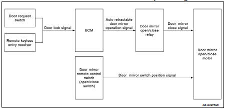
AUTO RETRACTABLE DOOR MIRORR FUNCTION : System Description
BCM retracts door mirror when door lock signal is received from Intelligent Key or door request switch.
OPERATION CONDITION
The system operates under the following conditions.
• Ignition switch: OFF
• Open/Close switch: AUTO
1. Press lock button of Intelligent Key or door request switch when the system is in operation condition.
2. Door mirror open/close relay turns ON for approximately 6 seconds. Door mirror is retracted.
NOTE
:
• Auto retractable door mirror system is not operated when BCM detects door lock
signal from power window
main switch of door key cylinder switch.
• ON/OFF of auto retractable door mirror system can be set on “WORK SUPPORT” of “INTELLIGENT KEY”of “BCM” using CONSULT-III. Refer to DLK-43, "INTELLIGENT KEY : CONSULT-III Function (BCM - INTELLIGENT KEY) (With Super Lock)" (With super lock) DLK-219, "INTELLIGENT KEY : CONSULT-III Function (BCM - INTELLIGENT KEY) (Without Super Lock)" (Without super lock).
 Component parts
Component Parts Location
1. Door request switch (driver side)
2. Door mirror (driver side)
3. Remote keyless entry receiver
Refer to DLK-21,
"Component Parts Location"
4. Door mirr ...
 Diagnosis system (BCM)
Common item
COMMON ITEM : CONSULT-III Function (BCM - COMMON ITEM)
APPLICATION ITEM
CONSULT-III performs the following functions via CAN communication with BCM.
SYSTEM APPLICATION
BCM can perfo ...
Other materials:
P0705 transmission range switch A
DTC Logic
DTC DETECTION LOGIC
DTC CONFIRMATION PROCEDURE
CAUTION:
Always drive vehicle at a safe speed.
NOTE:
If “DTC CONFIRMATION PROCEDURE” has been previously performed, always turn
ignition switch
OFF and wait at least 10 seconds before performing the next test.
After the repair, p ...
Power supply routing circuit
Wiring Diagram - Battery power supply -
For connector terminal arrangements, harness layouts, and alphabets in a
(option abbreviation; if not
described in wiring diagram), refer to GI-12, "Connector Information/Explanation
of Option Abbreviation".
Wiring Diagram - Accessory p ...
BCM
Removal and Installation
CAUTION:
Before replacing BCM, perform “READ CONFIGURATION” to save or print current
vehicle specification.
Refer to BCS-80, "ADDITIONAL SERVICE WHEN REPLACING CONTROL UNIT (BCM) :
Description".
REMOVAL (RHD MODELS)
1. Remove glove box assembly. Refer to I ...
