Nissan Juke Service and Repair Manual : System
System Diagram
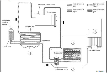
System Description
REFRIGERANT CYCLE
Refrigerant Flow
The refrigerant from the compressor, flows the condenser with liquid tank, the
evaporator, and returns to the
compressor. The refrigerant evaporation in the evaporator is controlled by an
expansion valve.
Freeze Protection
Automatic air conditioner • When intake sensor detects that evaporator surface temperature is 2°C (36°F) or less, A/C auto amp.
requests BCM to turn the compressor OFF.
• BCM requests ECM to turn the compressor to OFF by the signal from A/C auto amp., and ECM makes A/C relay to OFF, and stops the compressor.
Manual air conditioner
• When thermo control amp. detects that evaporator surface temperature becomes
2°C (36°F) or less, BCM
requests ECM to turn the compressor OFF, and stops the compressor.
REFRIGERANT SYSTEM PROTECTION
Refrigerant Pressure Sensor • The refrigerant system is protected against excessively high- or low-pressures by the refrigerant pressure sensor, installed at the condenser exit. The refrigerant pressure sensor detects the pressure inside the refrigerant line and sends the voltage signal to the ECM if the system pressure rises above, or falls below the specifications.
• ECM turns the A/C relay to OFF and stops the compressor when the high-pressure
side detected by refrigerant
pressure sensor is following conditions;
- Approximately 3,120 kPa (31.2 bar, 31.8 kg/cm2, 452 psi) or more (Engine speed
is less than 1,500 rpm.)
- Approximately 2,740 kPa (27.4 bar, 27.9 kg/cm2, 397 psi) or more (Engine speed
is 1,500 rpm or more.)
- Approximately 120 kPa (1.2 bar, 1.2 kg/cm2, 17 psi) or less
Pressure Relief Valve The refrigerant system is also protected by a pressure relief valve, located in the rear head of the compressor.
The release port on the pressure relief valve automatically opens and releases refrigerant into the atmosphere when the pressure of refrigerant in the system increases to an unusual level [more than 3,800 kPa (38 bar, 38.8 kg/cm2, 551 psi)].
 Component parts
Component Parts Location
1. Expansion valve
2. Condenser
3. Compressor
4. Liquid tank
5. Refrigerant pressure sensor
6. Evaporator
A. Built-in heater & cooling unit assembly
Componen ...
 Basic inspection
...
Other materials:
Oil filter
Removal and Installation
REMOVAL
1. Remove engine under cover.
2. Using oil filter wrench [SST: KV10115801] (A), remove oil filter.
: Vehicle front
CAUTION:
• Oil filter is provided with relief valve. Use genuine NISSAN
oil filter or equivalent.
• Be careful not to get burned when engine and ...
Engine emits blue smoke
Description
CHART 19: ENGINE EMITS BLUE SMOKE
Diagnosis Procedure
1.CHECK ENGINE OIL
Check the grade of engine oil. Refer to LU-33, "Inspection".
Is the inspection result normal?
YES >> GO TO 2.
NO >> Replace engine oil. Refer to LU-34, "Refilling".
2.CH ...
Fan control amplifier
Exploded View
1. A/C unit assembly
2. Fan control amp.*1
3. Blower fan resistor*2
4. Blower motor
5. Blower motor cover
• *1: Automatic air conditioner
• *2: Manual air conditioner
Removal and Installation
REMOVAL
1. Remove instrument panel assembly. Refer to IP-13, "Removal and ...
