Nissan Juke Service and Repair Manual : System
EPS system : System Description
• EPS control unit performs an arithmetical operation on data, such as steering wheel turning force (sensor signal) from the torque sensor, vehicle speed signal, etc. Then it generates an optimum assist torque signal to the EPS motor according to the driving condition.
• In case of an error in the electrical system, the fail-safe function stops output signals to the EPS motor. Refer to STC-9, "EPS SYSTEM : Fail-Safe".
• EPS control unit decreases the output signal to EPS motor while extremely using the power steering function (e.g., full steering) consecutively for protecting EPS motor and EPS control unit (Overload protection control). Refer to STC-9, "EPS SYSTEM : Protection Function".
• EPS control unit will decrease assistance under the following 2 conditions.
- Extensive steering at low speed will cause the EPS control unit and EPS motor to heat up, once temperature reaches critical point EPS control unit will reduce current to reduce heat up. System will recover as temperature lowers (reduced or no assistance).
- Holding steering on rack-end (full lock) for 1 second will cause the system to engage rack-end protection. This reduces assistance down to 50% in order to prevent heat up. Assistance is immediately returned to 100% when steering released or turned away from rack-end.
• In SPORT mode, changes the steering assist characteristic to enhance a stable steering feel according to the mode signals from multi display unit via CAN communication. (Models with Nissan Dynamic Control System)
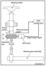
SYSTEM DIAGRAM
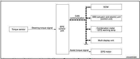
Multi display unit is applied to models with Nissan Dynamic Control System.
INPUT/OUTPUT SIGNAL
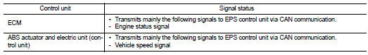
Communicates the signal from each control unit via CAN communication.
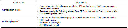
*: Models with Nissan Dynamic Control System
EPS WARNING LAMP INDICATION
• Turn ON when there is a malfunction in EPS system. If indicates that fail-safe mode is engaged and enters a manual steering state (Control turning force steering wheel becomes heavy).
• Also turns ON when ignition switch is turned ON, for purpose of lamp check. Turns OFF after the engine starts, if system is normal.
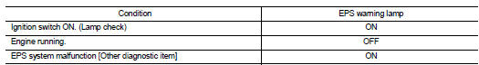
CAUTION:
EPS warning lamp also turns ON due to data reception error, CAN communication
error etc.
EPS system : Fail-Safe
• If any malfunction occurs in the system, and control unit detects the malfunction, EPS warning lamp on combination meter turns ON to indicate system malfunction.
• When EPS warning lamp is ON, enters into a manual steering state. (Control turning force steering wheel becomes heavy.)
EPS system : Protection Function
EPS control unit decreases the output signal to EPS motor while extremely using the power steering function (e.g., full steering) consecutively for protecting EPS motor and EPS control unit (Overload protection control).
While activating overload protection control, the assist torque gradually decreases, and the steering wheel turning force becomes heavy. The normal assist torque is recovered if the steering wheel is not turned for a while.
 Component parts
Component Parts Location
LHD models
1. Multi display unit*
Refer to DMS-3, "Component Parts
Location".
2. ABS actuator and electric unit (control
unit)
Refer to BRC-9, "Compone ...
 Diagnosis system (EPS control unit)
Consult-III Function
FUNCTION
CONSULT-III can display each diagnostic item using the diagnostic test modes
shown following.
*: The following diagnosis information is erased by erasing.
• DTC
...
Other materials:
Component parts
CVT control system : Component Parts Location
1. Multi display unit (MDU)*
Refer to DMS-3, "Component Parts
Location".
2. Combination meter 3. S mode indicator
(On the combination meter)
4. Shift position indicator
(On the combination meter)
5. Malfunction indicator lamp (MIL)
( ...
ASCD main switch
Component Function Check
1.CHECK ASCD MAIN SWITCH FUNCTION
1. Turn ignition switch ON.
2. Check the voltage between ECM harness connector terminals under the following
conditions.
Is the inspection result normal?
YES >> INSPECTION END
NO >> Go to EC-1009, "Diagnosis Proced ...
P2138 APP sensor
DTC Logic
DTC DETECTION LOGIC
NOTE:
If DTC P2138 is displayed with DTC P0643, first perform the trouble diagnosis
for DTC P0643. Refer to
EC-307, "DTC Logic".
DTC CONFIRMATION PROCEDURE
1.PRECONDITIONING
If DTC Confirmation Procedure has been previously conducted, always perform ...
