Nissan Juke Service and Repair Manual : System
Starting system (with intelligent key) : System Diagram
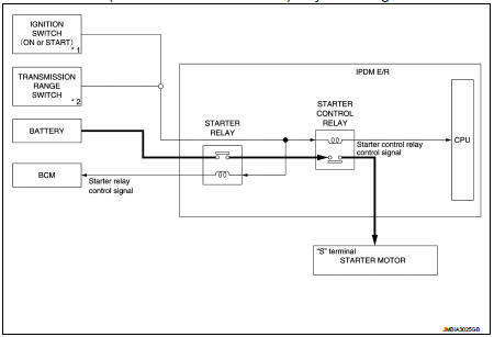
*1: M/T models
*2: CVT models
Starting system (with intelligent key) : System Description
CVT MODELS
• When selector lever is P or N, power is supplied to starter relay and starter control relay by transmission range switch. And BCM and IPDM E/R (CPU) detect selector lever P/N condition by the inputted signal.
• When starter operating condition is satisfied, IPDM E/R turns starter control relay ON by starter control relay control signal.
• When engine cranking condition is satisfied, BCM turns starter relay ON by starter control relay control signal.
• Then battery power is supplied to starter motor (“S” terminal) through starter control relay and starter relay.
M/T MODELS
• When the ignition switch is turned ON or START position power is supplied to starter relay and starter control relay. And BCM and IPDM E/R (CPU) detect ignition switch position by the inputted signal.
• When starter operating condition is satisfied, IPDM E/R turns starter control relay ON by starter control relay control signal.
• When engine cranking condition is satisfied, BCM turns starter relay ON by starter control relay control signal.
• Then battery power is supplied to starter motor (“S” terminal) through starter control relay and starter relay.
Starting system (without intelligent key) : System Diagram
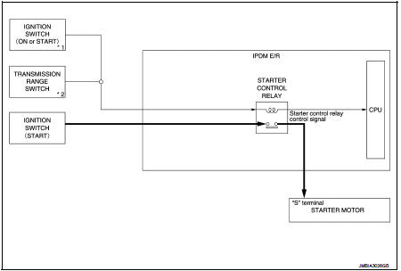
*1: M/T models
*2: CVT model
Starting system (without intelligent key) : System Description
CVT MODELS
• When selector lever is P or N, power is supplied to starter control relay by transmission range switch. And IPDM E/R (CPU) detect selector lever P/N condition by the inputted signal.
• When engine cranking condition is satisfied, then battery power is supplied to starter motor (“S” terminal) through starter control relay.
M/T MODELS
When ignition switch is START position, battery power is supplied to starter motor (“S” terminal).
 Component parts
Starting system (with intelligent key) : Component Parts Location
1. IPDM E/R
Refer to PCS-5, "Component Parts
Location".
2. Transmission range switch (CVT
models)
Refer to TM-131, & ...
 Wiring diagram
...
Other materials:
Power door lock system
System Diagram
System Description
DOOR LOCK FUNCTION
• The door lock and unlock switch (driver side) is build into power window
main switch.
• Interlocked with the locking operation of door lock and unlock switch, door
lock actuators of all doors are
locked.
• Interlocked with the unlock ...
Driver air bag module
Exploded View
1. Steering column upper cover
2. Steering column assembly
3. Steering column lower cover
4. Side lid LH
5. TORX bolt
6. Driver air bag module
7. TORX bolt
8. Side lid RH
9. Steering wheel
10. Spiral cable
11. Steering angle sensor
12. Combination switch
13. Stee ...
Emission control system warranty
Your NISSAN is covered by the following emission warranties.
For USA:
• Emission Defects Warranty
• Emissions Performance Warranty
Details of these warranties may be found with other vehicle warranties in your
Warranty Information Booklet which comes with your NISSAN. If you did no ...
