Nissan Juke Service and Repair Manual : Stop lamp switch
Component Function Check
1.CHECK STOP LAMP SWITCH OPERATION
Depress brake pedal and check that stop lamp turns ON, or release brake pedal and check stop lamp turns OFF.
Is the inspection result normal? YES >> GO TO 2.
NO >> Check stop lamp system. Refer to EXL-39, "Wiring Diagram".
2.CHECK DATA MONITOR
With CONSULT-III.
1. Turn the ignition switch OFF to ON.
2. Select “ABS”, “DATA MONITOR” and “STOP LAMP SW” according to this order. Check that data monitor displays “On” or “Off” when brake pedal is depress or release. Refer to BRC-27, "Reference Value".
Is the inspection result normal? YES >> INSPECTION END
NO >> Proceed to BRC-67, "Diagnosis Procedure".
Diagnosis Procedure
1.CHECK STOP LAMP SWITCH CLEARANCE
1. Turn the ignition switch OFF.
2. Check stop lamp clearance.
- LHD: Refer to BR-9, "Inspection and Adjustment".
- RHD: Refer to BR-77, "Inspection and Adjustment".
Is the inspection result normal? YES >> GO TO 2.
NO >> Adjust stop lamp switch clearance.
• LHD: Refer to BR-9, "Inspection and Adjustment".
• RHD: Refer to BR-77, "Inspection and Adjustment".
2.CHECK STOP LAMP SWITCH
Check stop lamp switch. Refer to BRC-68, "Component Inspection".
Is the inspection result normal? YES >> GO TO 3.
NO >> Repair or replace stop lamp switch.
• LHD: Refer to BR-21, "Removal and Installation".
• RHD: Refer to BR-89, "Removal and Installation".
3.CHECK STOP LAMP SWITCH CIRCUIT (1)
1. Turn the ignition switch OFF.
2. Disconnect ABS actuator and electric unit (control unit) harness connector.
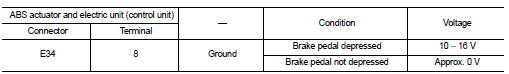
3. Check voltage between ABS actuator and electric unit (control unit) harness connector and ground.
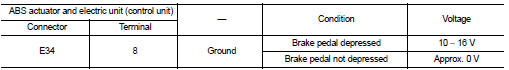
4. Turn the ignition switch ON.
CAUTION:
Never start engine.
5. Check voltage between ABS actuator and electric unit (control unit) harness connector and ground.
Is the inspection result normal? YES >> GO TO 6.
NO >> GO TO 4.
4.CHECK STOP LAMP SWITCH CIRCUIT (2)
1. Turn the ignition switch OFF.
2. Disconnect stop lamp switch harness connector.
3. Check continuity between ABS actuator and electric unit (control unit) harness connector and stop lamp switch harness connector.
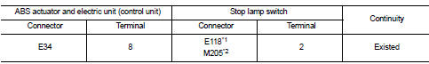
*1: LHD
*2: RHD
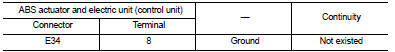
4. Check continuity between ABS actuator and electric unit (control unit) harness connector and ground.
Is the inspection result normal? YES >> GO TO 5.
NO >> Repair or replace error-detected parts.
5.CHECK STOP LAMP SWITCH POWER SUPPLY CIRCUIT
1. Check 10 A fuse (#38).
2. Check continuity and short circuit between stop lamp switch harness connector terminal (1) and 10 A fuse (#38).
Is the inspection result normal? YES >> Perform trouble diagnosis for battery power supply. Refer to PG-10, "Wiring Diagram - BATTERY POWER SUPPLY -".
NO >> Repair or replace error-detected parts.
6.CHECK TERMINAL
• Check ABS actuator and electric unit (control unit) pin terminals for damage or loose connection with harness connector.
• Check stop lamp switch pin terminals for damage or loose connection with harness connector.
Is the inspection result normal? YES >> Replace ABS actuator and electric unit (control unit). Refer to BRC-90, "Removal and Installation".
NO >> Repair or replace error-detected parts.
Component Inspection
1.CHECK STOP LAMP SWITCH
1. Turn the ignition switch OFF.
2. Disconnect stop lamp switch harness connector.
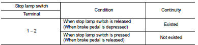
3. Check continuity when stop lamp switch is operated.
Is the inspection result normal? YES >> INSPECTION END
NO >> Replace stop lamp switch.
• LHD: Refer to BR-21, "Removal and Installation".
• RHD: Refer to BR-89, "Removal and Installation".
 Power supply and ground circuit
Diagnosis Procedure
1.CHECK ABS ACTUATOR AND ELECTRIC UNIT (CONTROL UNIT) IGNITION POWER
SUPPLY
1. Turn the ignition switch OFF.
2. Disconnect ABS actuator and electric unit (control unit) harnes ...
 Parking brake switch
Component Function Check
1.CHECK PARKING BRAKE SWITCH OPERATION
Operate the parking brake lever. Then check that the brake warning lamp in
the combination meter turns ON/
OFF correctly.
Is the ...
Other materials:
Push-button ignition switch illumination circuit
Description
Provides the power supply and the ground to control the push-button ignition
switch illumination.
Component Function Check
1.CHECK PUSH-BUTTON IGNITION SWITCH ILLUMINATION OPERATION
CONSULT-III ACTIVE TEST
1. Turn the ignition switch ON.
2. Select “ENGINE SW ILLUMI” of BCM (INTEL ...
P0745 pressure control solenoid A
DTC Logic
DTC DETECTION LOGIC
DTC CONFIRMATION PROCEDURE
NOTE:
If “DTC CONFIRMATION PROCEDURE” has been previously performed, always turn
ignition switch
OFF and wait at least 10 seconds before performing the next test.
After the repair, perform the following procedure to confirm the mal ...
B1182 lap Pre-tensioner LH
DTC Logic
DTC CONFIRMATION PROCEDURE
1.CHECK SELF-DIAGNOSTIC RESULT
With CONSULT-III
1. Turn ignition switch ON.
2. Perform “Self Diagnostic Result” mode of “AIR BAG” using CONSULT-III.
Without CONSULT-III
1. Turn ignition switch ON.
2. Check the air bag warning lamp status. Refer to SRC ...
