Nissan Juke Service and Repair Manual : Steering wheel
Exploded View
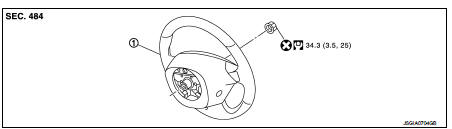
1. Steering wheel
 : Always replace after every
disassembly.
 : N·m (kg-m, ft-lb)
Removal and Installation
REMOVAL
NOTE
:
When reconnecting spiral cable, fix cable with a tape so that fixing case and
rotating part keep aligned. This
will omit neutral position alignment procedure during spiral cable installation.
1. Set vehicle to the straight-ahead position.
2. Remove driver air bag module. Refer to SR-13, "Removal and Installation".
3. Remove steering wheel lock nut after steering is locked.
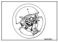
4. Remove steering wheel with the steering wheel puller (A) (SST: ST27180001)
INSTALLATION
Note the following, and install in the reverse order of removal.
• Check the spiral cable neutral position after replacing or rotating spiral cable. Refer to SR-16, "Removal and Installation".
CAUTION:
Never twist spiral cable excessively after it becomes tight. (Twisting may cause
the cable to be torn
off.)
• Never reuse steering wheel lock nut.

 Steering column
Exploded View
1. Cover
2. Sub-harness
3. Band
4. Steering column assembly
5. Slide plate (inner)
6. Slide plate (outer)
7. Bracket
Always replace after every
disassembly.
: N·m (kg-m ...
Other materials:
U1000 can comm circuit
Description
CAN (Controller Area Network) is a serial communication line for real time
applications. It is an on-board multiplex
communication line with high data communication speed and excellent error
detection ability. A modern
vehicle is equipped with many ECMs, and each control unit shar ...
Evaporative emission system
Evaporative emission system: System
Diagram
Evaporative emission system : System
Description
INPUT/OUTPUT SIGNAL CHART
*: ECM determines the start signal status by the signals of engine speed and
battery voltage.
SYSTEM DESCRIPTION
The evaporative emission system is used to reduce hy ...
P2100 electric throttle control function
DTC Logic
DTC DETECTION LOGIC
Diagnosis Procedure
1.CHECK GROUND CONNECTION
1. Turn ignition switch OFF and wait at least 4 minutes.
2. Check ground connection E38. Refer to Ground inspection in GI-44, "Circuit
Inspection".
Is the inspection result normal?
YES >> GO TO 2 ...
